Optical fibre sensor with variable precision

A fiber optic sensor and variable precision technology, applied in the field of sensors, can solve the problems of inability to accurately measure the liquid level in real time, high precision limitations, etc., and achieve variable precision liquid level measurement, high precision accurate measurement, and high measurement accuracy Effect

Inactive Publication Date: 2008-09-03
XI AN JIAOTONG UNIV +1
View PDF0 Cites 10 Cited by
  • Summary
  • Abstract
  • Description
  • Claims
  • Application Information

AI Technical Summary

Problems solved by technology

The sensor can not only solve the problem that the electrical measurement method is limited by safety, large range, and high precision in the case of inflammable and explosive substances, but also solve the problem that the liquid level cannot be accurately measured in real time due to the influence of weightlessness. It has a simple structure , Low production cost, strong anti-electromagnetic interference ability, good corrosion resistance

Method used


Image

  • Optical fibre sensor with variable precision
  • Optical fibre sensor with variable precision
  • Optical fibre sensor with variable precision

Examples


Embodiment 1

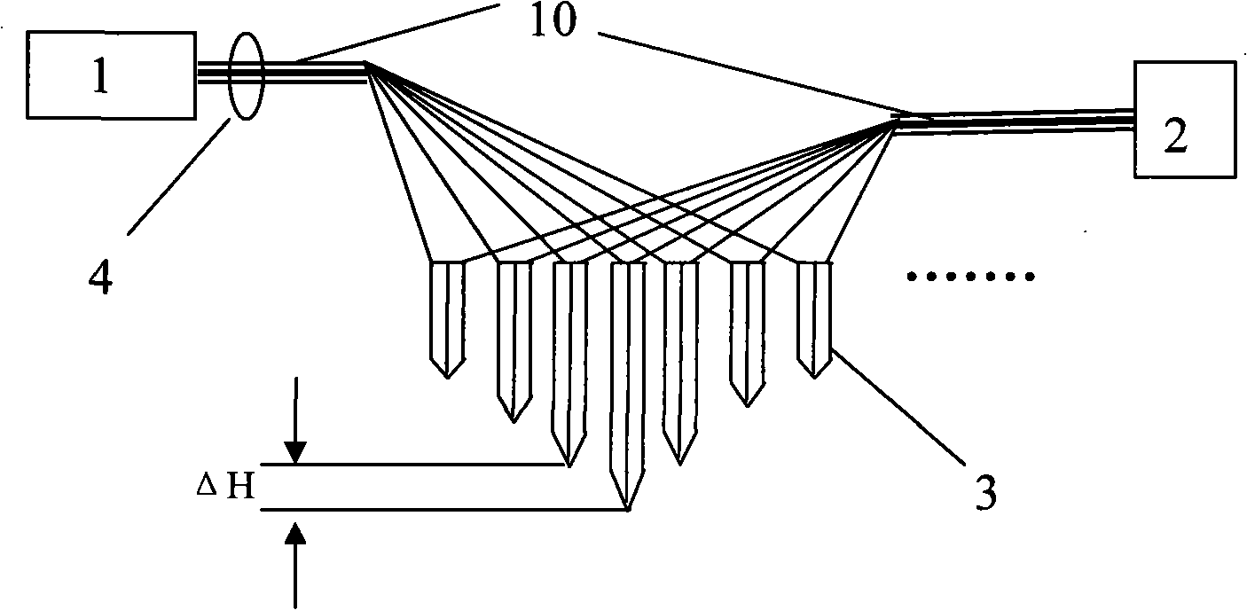
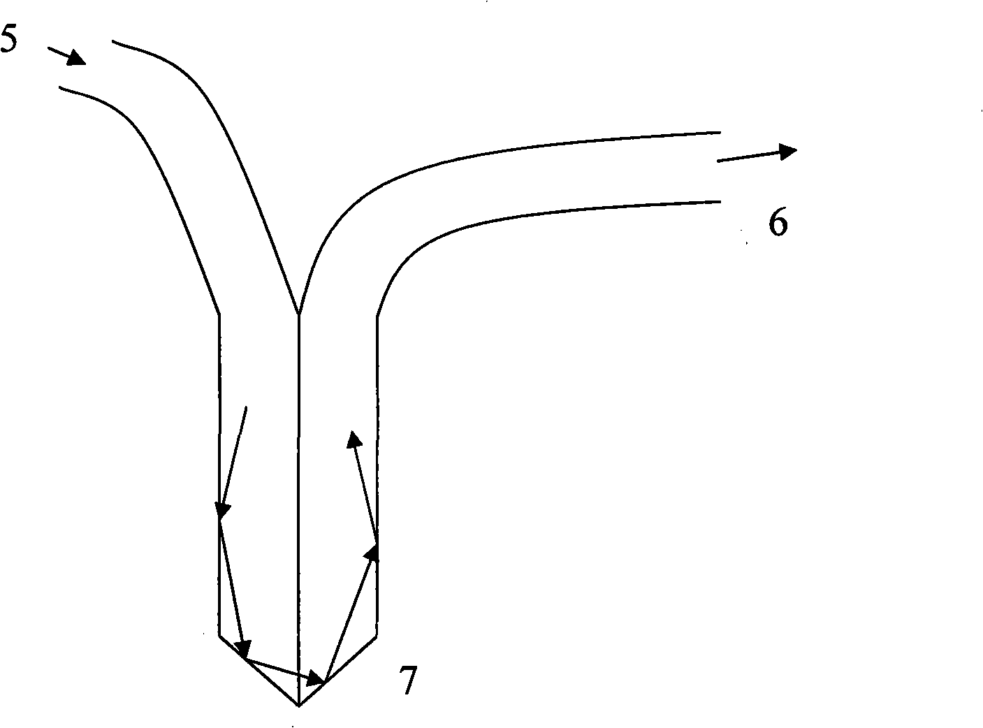
[0024] see figure 1 , figure 2 , a liquid level measurement sensor with variable precision, consisting of a light source 2 (laser or photodiode), a dual fiber optic probe 2 and an optical cable 10, a focusing lens 4, and a light receiving device 1 (CCD, CMOS, photodiode, etc.). Multiple dual fiber optic probes 2 are arranged according to a certain height difference ΔH. Each double fiber optic probe 2 can achieve a certain range of measurement accuracy through the height difference ΔH. Extend the dual fiber optic probes 2 into the measured liquid to the bottom. According to the formula n1Sinθ1=n2Sinθ2, when the refractive index n2 becomes larger, the refraction angle θ2 decreases, and when the refractive indices of the two media are closer, the closer Total reflection is not easy to occur, that is, the light is directly refracted into the second medium, which is why the light intensity at the exit end of the dual fiber optic probe 2 will be darker when immersed in the liquid...

Embodiment 2

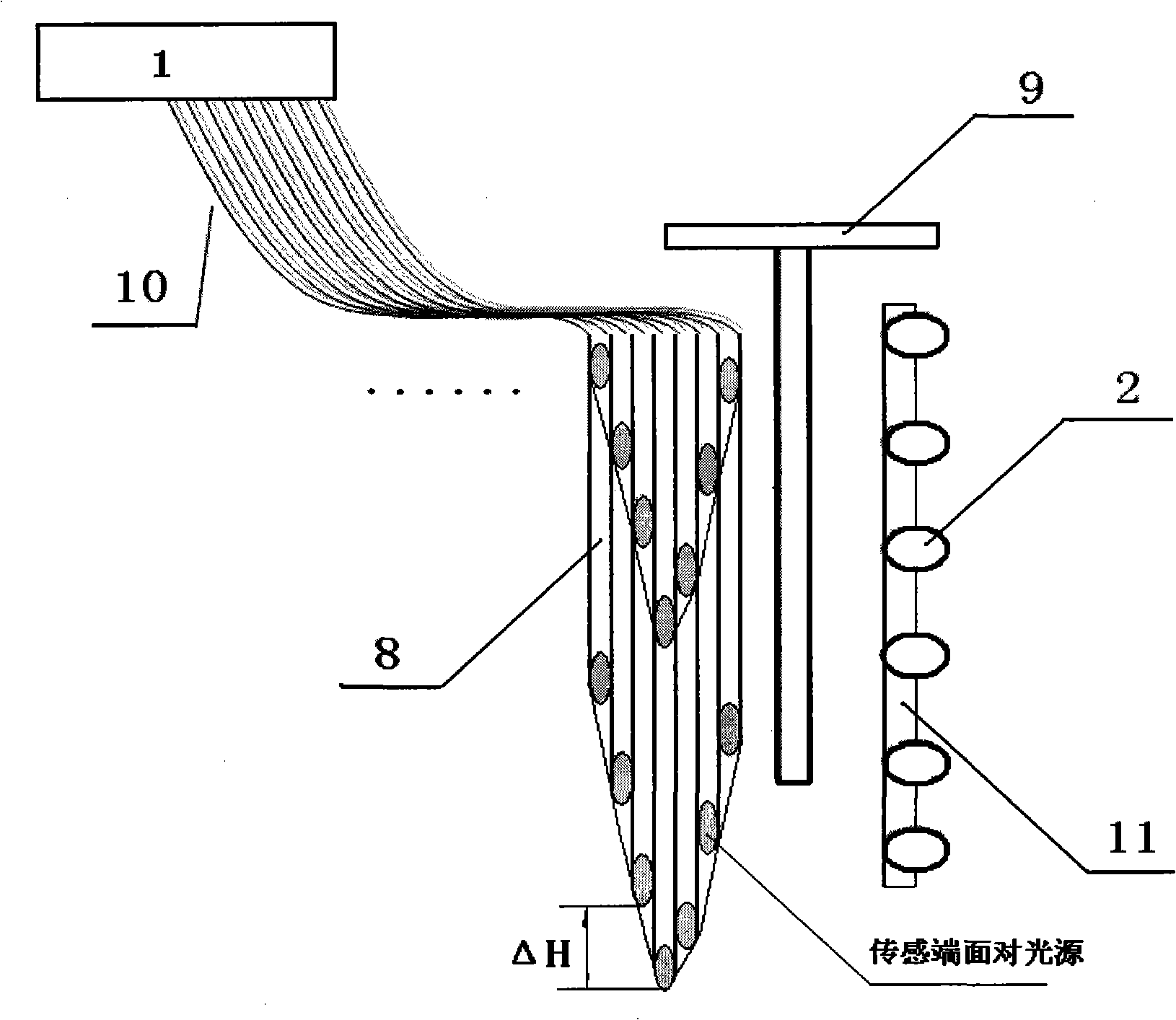
[0028] see image 3 , a variable precision displacement measurement sensor, the optical fiber displacement sensor is composed of a light source 2, a single optical fiber probe 8 and an optical cable 10, a shading plate 9, a light receiving device 1 and the like. The light source 2 is composed of a plurality of light-emitting diodes from bottom to top to form a linear point light source, and is converted into a relatively uniform line light source through a uniform light plate 11 (such as frosted glass, etc.) that uniformizes the light. A plurality of single-fiber probes 8 are arranged according to a certain height difference ΔH, and the light incident end of each single-fiber probe 8 forms a 45° inclined plane with the fiber core axis to form a sensing end face and is opposite to the light-emitting diode; A light-shielding plate 9 that can move up and down is arranged between them; the optical fiber at the light output end of each single fiber probe 8 is led out to form an opt...


PUM


Abstract

The invention discloses a variable-precision optical fiber sensor, which includes a probe, a light source and an optical receiver, the light source and the optical receiver are separately connected with probe through luminiferous medium in luminiferous connection, which is characterized in that the probe is a double optical fiber probe including sensor end, light incidence end and light emergence end, lots of the double optical fiber probes are arranged in a row on the surface, every double optical fiber probe sensor end is arranged according to height difference delta H; the luminiferous medium is cable, which is composed of optical fiber bundle comprising optical fiber induced from light incidence end or light emergence end of every double optical fiber probe; the double optical fiber probe with height difference delta H is arranged in space to form a multi-row with height difference delta H'. The invention can be used for testing liquid level in inflammable and explosive fluid, which has the characteristics of simple structure, low producing cost, strong capability of anti-electromagnetism and anti-interference, and anti-corrosion.

Description

technical field [0001] The invention relates to a sensor, in particular to a variable precision optical fiber sensor used for liquid level detection inside flammable and explosive liquids and for measuring deformation and displacement of bridges and dams. Background technique [0002] In the existing sensor technology field, the detection of the liquid surface position can be roughly divided into electric contact type liquid level sensors, float type liquid level sensors, ultrasonic radar and microwave liquid level sensors. For the electric contact liquid level sensor, because it uses the conductivity of the measured medium to detect the liquid level, it is only limited to the liquid medium with conductive properties, and has direct electrical contact with the measured medium, and is not suitable for easy Liquid level measurement of flammable and explosive liquid media; for float type liquid level sensors, due to the relative movement of mechanical parts, mechanical failures...

Claims


Application Information

Patent Timeline
Patent Type & Authority Applications(China)
IPC IPC(8): G01D5/353G01F23/292G02B6/44G02B6/26
Inventor 乐开端于宁宁
Owner XI AN JIAOTONG UNIV
Why Eureka
Try Eureka