Improved perfluorinated membranes and improved electrolytes for redox cells and batteries

A battery pack and electrolyte technology, applied in the direction of battery electrodes, electrode manufacturing, fuel cell components, etc.

Inactive Publication Date: 2008-09-03
NEWSOUTH INNOVATIONS PTY LTD
View PDF5 Cites 26 Cited by
  • Summary
  • Abstract
  • Description
  • Claims
  • Application Information

AI Technical Summary

Problems solved by technology

The improved electrodes and electrode preparation methods do not suffer from the surface degradation previously experienced with carbon-filled polyolefin / rubber composites

Method used


Image

  • Improved perfluorinated membranes and improved electrolytes for redox cells and batteries
  • Improved perfluorinated membranes and improved electrolytes for redox cells and batteries
  • Improved perfluorinated membranes and improved electrolytes for redox cells and batteries

Examples


Embodiment 1

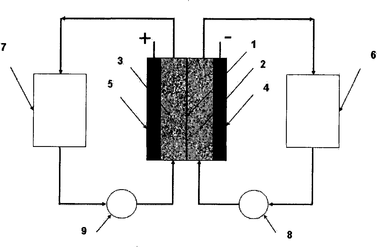
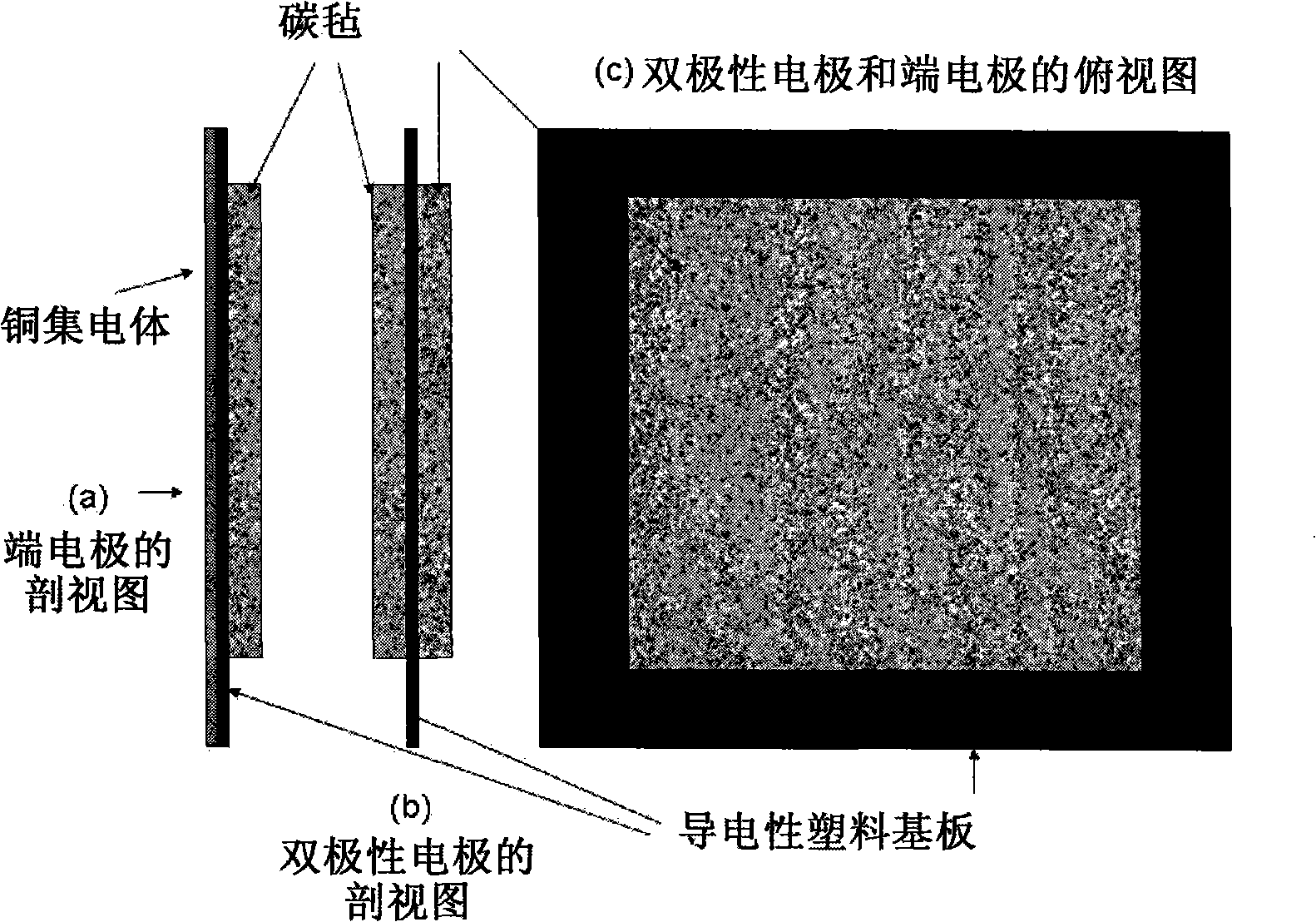
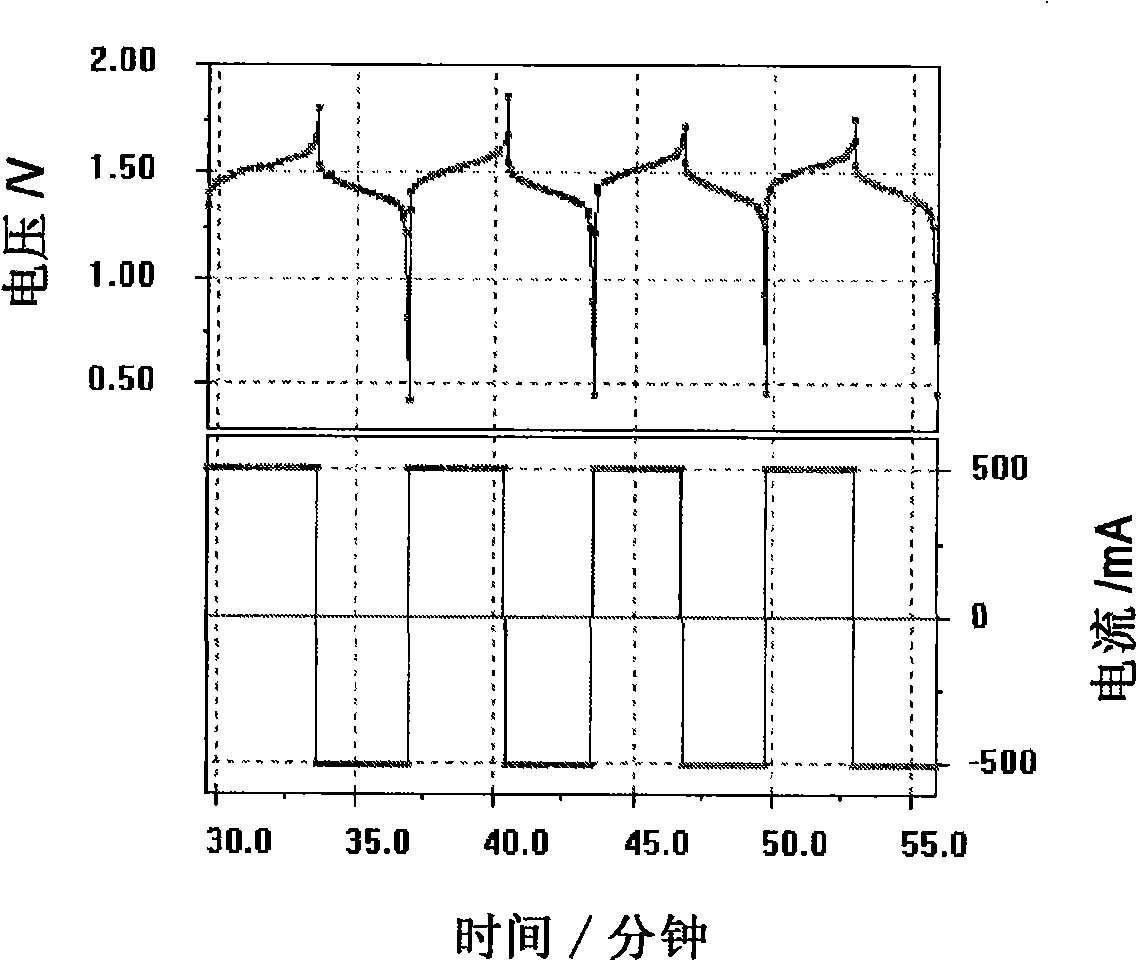
[0058] Two carbon felt / conductive plastic electrodes according to the invention were prepared by placing a conductive plastic sheet with a composition of 20% carbon black and 80% high-density polyethylene in a mould, and in the mould, , a piece of copper felt was placed on one side of the conductive plastic, and a 5 cm x 5 cm Sigri felt was placed on the opposite side. The mold was closed and heated to 240°C by placing it on a heated platen. A 125kg weight was placed on top of the mold for 15 minutes. The mold is then removed from the heated platen and allowed to cool to room temperature. Two terminal electrodes thus prepared were used in a vanadium redox cell. First dip the carbon felt in 5M H 2 SO 4 In a solution of 0.9M V(III) and 0.9M V(IV) in the medium, the electrode is placed between two flow frames with a cast-formed perfluorinated film (by sandwiched between two end plates). Cycling was performed with a battery charge and discharge current of 500mA.

[0059] Th...

Embodiment 2

[0061] A bipolar electrode of the present invention was prepared by placing 5 cm x 5 cm Sigri carbon felt on either side of the conductive plastic sheet of Example 1 in a mold and heating to 230°C. A 100 kg weight was placed on top of the mold for 15 minutes. The mold was then cooled to room temperature and the conductivity of the electrode was tested by placing it between two copper sheets and passing a current of 1 amp. After subtracting the voltage drop across the current collector, the recorded voltage drop for the bipolar electrode was 50 mV. Using Ohm's law and an electrode area of ​​25cm 2 Under the conditions, the resistivity of the bipolar electrode was determined to be 1.25 ohm cm 2 .

[0062] A second experiment was performed using the same temperature and pressure, except that the bonding time was increased to 20 minutes. The resistivity of the prepared bipolar electrode is about 1 ohm cm 2 .

Embodiment 3

[0064] Bipolar electrodes were prepared by the following steps: two carbon felts with a size of 400 mm × 400 mm were respectively placed on a conductive plastic (composed of 20% carbon black and 80% high carbon black) with a thickness of 1 mm and a size of 600 mm × 600 mm density polyethylene) on both sides of the sheet. By applying 2.5kg·cm at 230°C -2 The pressure was 15 minutes, and the carbon felt was thermally bonded to both sides of the conductive plastic sheet respectively. After cooling to room temperature, the conductivity of the resulting electrode was tested by placing 2 pieces of copper on both sides of the bipolar electrode and applying a current of 10 amps to the copper pieces. It was found that the conductivity of the bipolar electrode was 0.8 ohm cm 2 to 1.2 ohm·cm 2 .


PUM

PropertyMeasurementUnit
thicknessaaaaaaaaaa
thicknessaaaaaaaaaa
thicknessaaaaaaaaaa

Abstract

The invention relates to an electrode used for vanadium redox flow battery, a preparation of electrolyte and a rebalance method. The preparation comprises thermally sticking a carbon felt or agraphite felt to at least one side of a carbon-filled polyolefine substrate. A flat, low-resistance electrode having good mechanical property can be obtained by the preparation. The preparation includes dissolving at least one vanadium oxide powder to a supporting electrolyte and optional electrolysis steps. The preparation needs no toxic SO2 gas, by separating the power dissolving stage and the electrolysis stage, problems related to suspension powder electrolysis are eliminated. The rebalance method comprises partially reducing a half-cell electrolyte in the cathode chamber of an electrolytic cell.

Description

technical field [0001] The present invention describes improved methods for preparing electrodes and electrolytes for use in vanadium redox flow batteries and batteries. A vanadium redox flow battery (collectively referred to herein as VFB) includes a V(II) / V(III) pair in the negative half-cell and a V(IV) / V(V) pair in the positive half-cell. All vanadium redox cells and batteries (referred to herein as V / VRBs). [0002] In V / VRB, each cell produces a cell voltage of 1.1V to 1.6V depending on the state of charge, but multiple cells can be electrically connected in series using bipolar electrodes to obtain a cell stack with a specific desired value or battery pack. Electrodes for redox battery applications must have the following properties: low cost, chemical stability against the strong oxidative conditions in the positive half-cell, good electrocatalytic performance for redox battery reactions, good mechanical properties, Has low permeability to electrolyte, and has low r...

Claims


Application Information

Patent Timeline
Patent Type & Authority Applications(China)
IPC IPC(8): H01M4/88H01M4/04H01M8/18H01M8/20H01M10/36H01M8/02H01M10/02
CPCY02E60/10Y02E60/50
Inventor 尼古拉斯·迈克尔·卡扎科斯迈克尔·卡扎科斯乔治·克里斯托弗·卡扎科斯玛丽亚·斯凯拉斯-卡扎科斯
Owner NEWSOUTH INNOVATIONS PTY LTD
Why Eureka
Try Eureka