

Forming method and forming device for battery shell
A technology for battery casings and pressure plates, which is applied in the direction of batteries, battery pack parts, chemical instruments and methods, etc., which can solve the problems of easy breakage of aluminum foil, increased pressure of anti-wrinkle pressure plates, and higher degree of bulge forming, etc., to achieve excellent Effect of deep drawing formability, improvement of material yield, and expansion of application range
Active Publication Date: 2008-09-10
株式会社力森诺科包装
View PDF3 Cites 27 Cited by
- Summary
- Abstract
- Description
- Claims
- Application Information
AI Technical Summary
Problems solved by technology
[0009] However, in the case of using the coil spring as the pressure applying mechanism of the wrinkle-preventing plate member as described in the above-mentioned prior art, since the deeper the forming depth of the drawing process is, the compression degree of the coil spring during forming is increased, and accordingly The pressure of the anti-wrinkle platen increases, and the forming material is firmly clamped between the anti-wrinkle platen part and the die.
[0010] Therefore, in the conventional deep drawing process by press forming, especially when the forming sheet made of the above-mentioned laminated material is used as the forming object, it is difficult to carry out comparison because the aluminum foil tends to break during material stretching. Deep forming, and since the coil spring is in elastic contact with multiple positions of the anti-wrinkle platen part of the stamping mold, it may cause uneven pressure on the anti-wrinkle platen and cause wrinkles
In addition, in terms of cost, if a standardized coil spring is used, it is difficult to obtain the most suitable anti-wrinkle platen pressure suitable for the formed shape, and it is necessary to replace the coil with appropriate strength according to the size and depth of the formed shape. Spring, this replacement operation wastes a lot of labor and time
Method used
View moreImage
Smart ImageViewing Examples

Examples
Embodiment 1
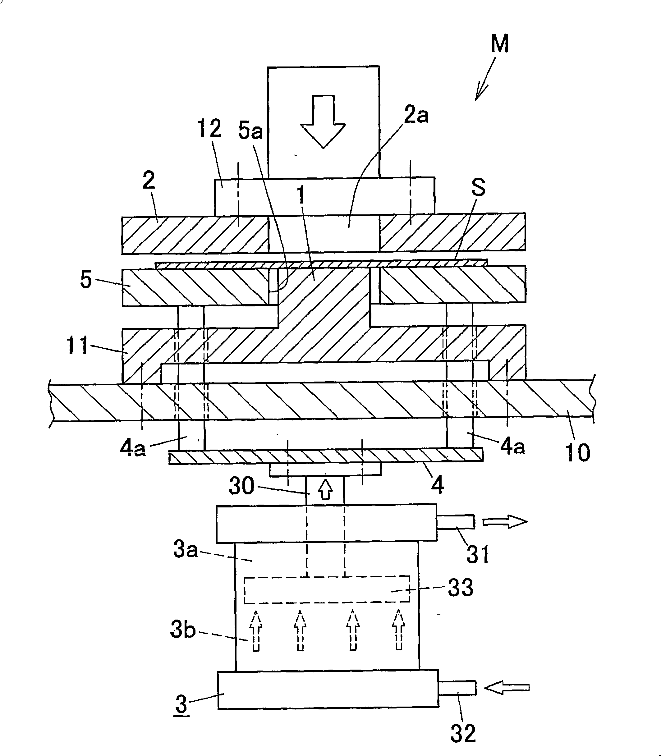
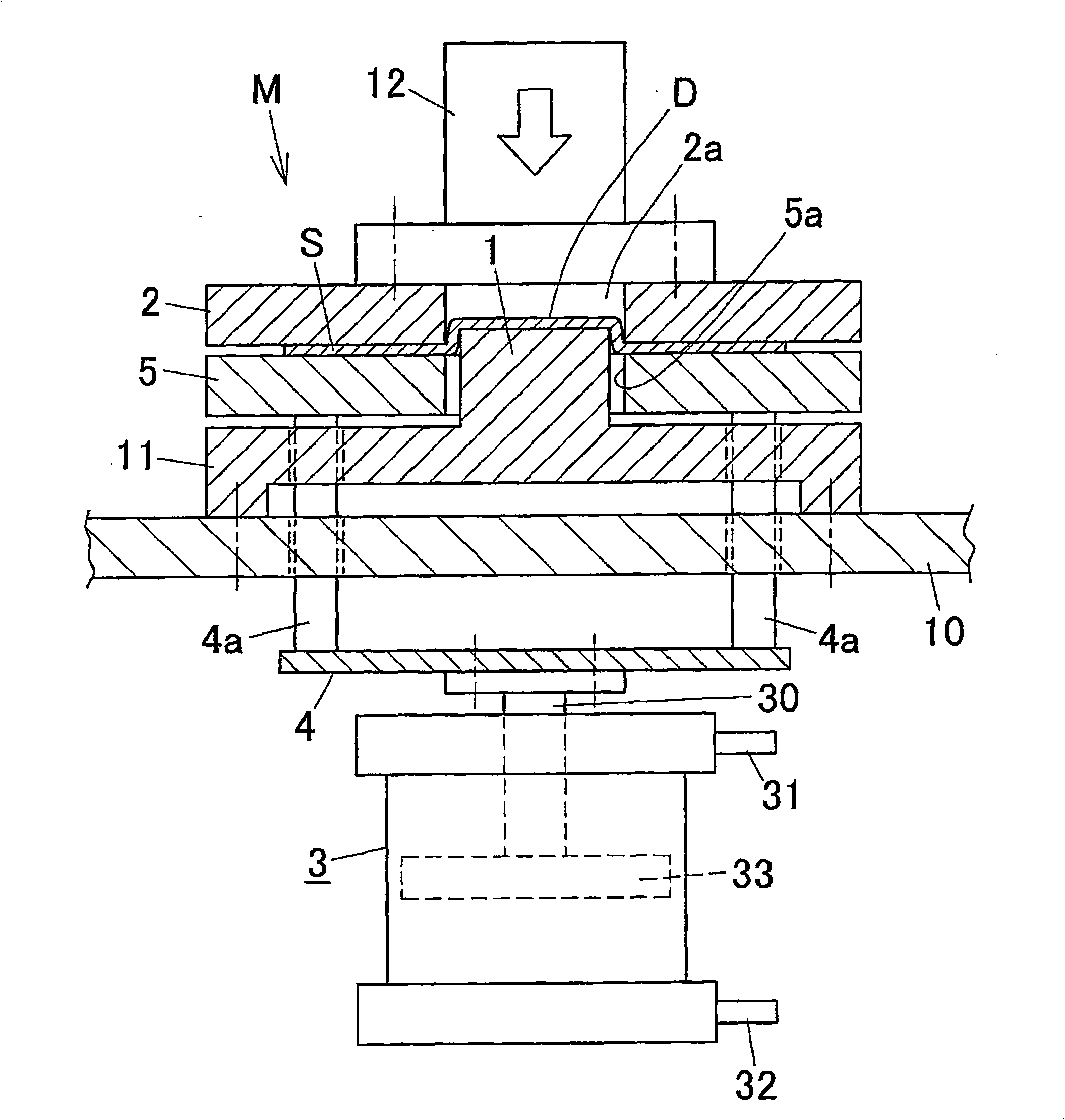
[0066] in such as figure 2 In the shown forming apparatus M having a press forming die (forming height free) having the above-mentioned structure, a forming sheet S having a blank shape of 110×180 mm was formed as As for the material, a battery case was produced by performing one-stage deep drawing with a forming height of 5 mm and one-stage deep drawing with a forming height of 6 mm.
Embodiment 2
[0068]A battery case was produced in the same manner as in Example 1 except that the pressure of the anti-crease plate was set at 0.5 MPa.
Embodiment 3
[0070] A battery case was produced in the same manner as in Example 1 except that the pressure of the anti-crease plate was set to 0.1 MPa.
Login to View More PUM
| Property | Measurement | Unit |
|---|---|---|
| thickness | aaaaa | aaaaa |
| thickness | aaaaa | aaaaa |
| thickness | aaaaa | aaaaa |
Abstract
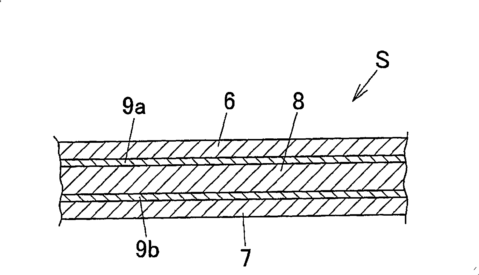
The invention provides a forming method of battery shell which is charactered in that: a forming sheet (S), which includes a resin film layer as an outside layer, a resin film layer as an inner layer and an aluminium foil layer between two film layers, is punch formed to required shape by a punch forming mould composed of a die (2), a former block (1) and a crease-resist pressure pad component (5). According with the forming method, in a deep pulling / processing process that punch forming is realized by the forming sheet with special lamination structure used as forming material, the crease-resist pressure pad pressure generated by the crease-resist pressure pad can be adjusted suitably according with forming shape size, deepness also likes. Consequently, more deep process can be processed easily and suitable range of forming shape is enlarged, and a deep pulling process without crease is processed.
Description
[0001] This application claims the priority of Japanese Patent Application No. 2007-54996 filed on March 6, 2007, and the disclosure thereof constitutes a part of the present application as it is. technical field [0002] The present invention relates to a method and a molding device for forming a battery case of a lithium rechargeable battery or the like used as a power source of portable electronic equipment such as a notebook computer, a video camera, and a mobile phone. Background technique [0003] In addition, within the scope of the specification and claims, the term "aluminum" includes aluminum and its alloys. In addition, the meaning of the word "film" includes "sheet". [0004] Battery cases (packages) such as lithium rechargeable batteries are produced by forming a sheet for forming made of a laminated material of aluminum foil and resin film into a predetermined square box shape by deep drawing by press forming. [0005] Generally, in such deep drawing by press ...
Claims
Login to View More Application Information
Patent Timeline
 Patent Type & AuthorityApplications(China)
IPC IPC(8): B21D22/22B21D24/08B32B27/06B32B15/08
CPCY02E60/10H01M2220/30B32B38/12B29C51/08H01M50/124H01M50/121H01M50/119
Inventor畑浩宫岛美道
Owner株式会社力森诺科包装