Supercharge Your Innovation With Domain-Expert AI Agents!

Sensing semiconductor and its making method

A technology of semiconductor and manufacturing method, which is applied in the field of sensing semiconductor devices, and can solve problems such as complex manufacturing process, high cost, and position deviation of inclined notches

Inactive Publication Date: 2008-09-10
SILICONWARE PRECISION IND CO LTD
View PDF2 Cites 3 Cited by
  • Summary
  • Abstract
  • Description
  • Claims
  • Application Information

AI Technical Summary

Problems solved by technology

[0005] However, in the aforementioned sensing type semiconductor device, since the inclined notch relationship was previously formed from the back side of the wafer, the side surface of the semiconductor device presents an oblique chamfered shape after the cutting operation, that is, its vertical section is an inverted trapezoid (plane width Gradually shorten from top to bottom) structure, so the metal winding formed on the side of the semiconductor device is in acute contact with the connection of the extension line of the pad on the top surface of the chip, and the problem of stress concentration causing the connection to break is prone to occur. Furthermore, In the manufacturing process, the inclined notch is formed from the back of the wafer. Because it is difficult to align to the correct position, it is easy to cause the setting position of the inclined notch to shift, resulting in the inability to connect the metal winding and the extension line, and even damage the chip.
[0006] In addition, because the metal winding is exposed outside the semiconductor device, it is susceptible to external contamination and affects product reliability, and it is easy to cause a short circuit during solder ball reflow when it is electrically connected to an external device (such as a printed circuit board). question
Furthermore, in the manufacturing process, extension lines and metal windings need to be formed successively, resulting in problems such as complicated manufacturing process and high cost.
[0007] Therefore, how to design a wafer-level chip size sensing semiconductor device and its manufacturing method that can avoid the problem of circuit breakage and exposure, and at the same time avoid the alignment error of cutting from the back of the wafer in the prior art. The problem of poor electrical connection and chip damage is indeed an urgent issue in related fields

Method used


Image

  • Sensing semiconductor and its making method
  • Sensing semiconductor and its making method
  • Sensing semiconductor and its making method

Examples


Embodiment Construction

[0042] The implementation of the present invention is described below through specific examples, and those skilled in the art can easily understand other advantages and effects of the present invention from the content disclosed in this specification.

[0043] see Figure 2A to Figure 2I , is a schematic diagram of a first embodiment of the sensing semiconductor device and its manufacturing method of the present invention. In the following, the mass production of the sensing semiconductor device of the present invention will be taken as an illustration.

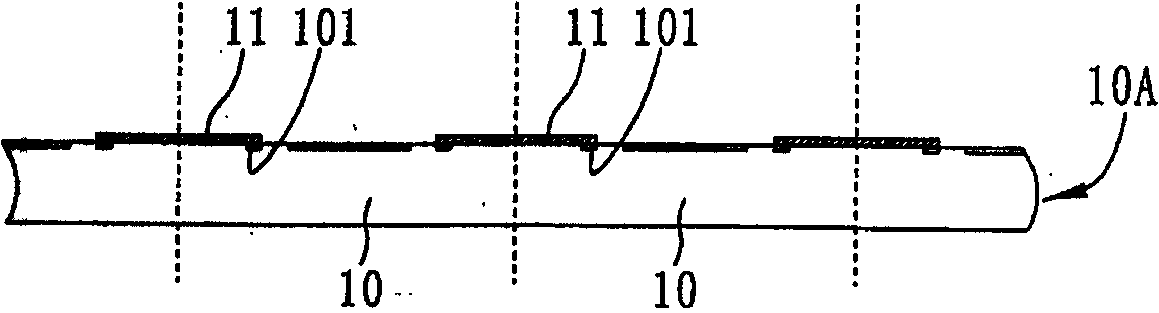
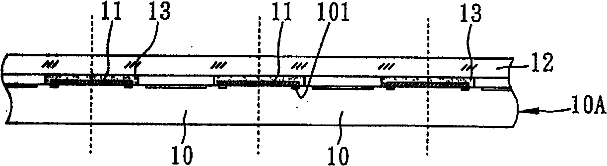
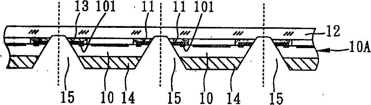
[0044] Such as Figure 2A As shown, a wafer 20A including a plurality of sensing chips 20 is provided. The sensing chip 20 has an active surface and a non-active surface opposite to each other. The active surface is provided with a sensing region 202 and a plurality of bonding pads 201, A plurality of grooves 203 are formed between the bonding pads 201 on the active surface of adjacent sensing chips 20 , wherein the grooves...


PUM


Abstract

The invention discloses a sensing semiconductor device and a preparation method thereof, comprising the main steps that: a plurality of concave grooves are formed between pads corresponding to the active surfaces of an adjacent sensing chip on a wafer with a plurality of sensing chips; a conducting circuit in electric connection with the pads of the adjacent sensing chip is formed inside the concave grooves; the wafer is connected with a light penetrating body to seal and cover the sensing area of the sensing chip; the inactive surface of the wafer is thinned to the conducting circuit and to expose the conducting circuit; the cutting is performed along each sensing chip so as to form a plurality of sensing chips with the side having the conducting circuit; afterwards, the sensing chips are arranged on base plate module plates of a plurality of base plates which are arranged in an array, the conducting circuit of the sensing chip is electrically connected with the base plate, an insulating material is filled on the base plate module plate corresponding to each sensing chip so as to wrap the sensing chip, and the cutting is performed along the base plate to form a plurality of sensing semiconductor devices, thus being capable of solving the problem existing in the prior art.

Description

technical field [0001] The present invention relates to a sensing type semiconductor device and a manufacturing method thereof, in particular to a sensing type semiconductor device of a wafer level chip size package (WLCSP) and a manufacturing method thereof. Background technique [0002] The traditional image sensor package mainly connects the sensor chip on a chip carrier, and electrically connects the sensor chip and the chip carrier through bonding wires. Afterwards, a glass is sealed above the sensing chip, so that the image light can be picked up by the sensing chip. In this way, the completed image sensing package can be used by the system factory to integrate on external devices such as printed circuit boards (PCBs) for digital cameras (DSC), digital video cameras (DV), optical mice, etc. , and mobile phones and other electronic products. [0003] At the same time, with the continuous expansion of information transmission capacity and the development trend of minia...

Claims


Application Information

Patent Timeline
IPC IPC(8): H01L21/50H01L21/60H01L27/146H01L23/485H01L23/488
CPCH01L2924/0002H01L2224/13
Inventor 詹长岳黄建屏张泽文黄致明萧承旭
Owner SILICONWARE PRECISION IND CO LTD
Features
  • R&D
  • Intellectual Property
  • Life Sciences
  • Materials
  • Tech Scout
  • Unparalleled Data Quality
  • Higher Quality Content
  • 60% Fewer Hallucinations
Learn More