Self-propelled type end cutter with smoothing blade

A technology for end mills and blades, which is applied in the field of self-rolling face milling cutters, and can solve problems such as increased cost, pollution, and blades that cannot be rotated

Inactive Publication Date: 2008-09-17
ZHONGBEI UNIV
View PDF1 Cites 22 Cited by
  • Summary
  • Abstract
  • Description
  • Claims
  • Application Information

AI Technical Summary

Problems solved by technology

[0002] In mechanical processing, metal cutting tools are very important. In aerospace, aviation and military industries, there are more and more difficult-to-machine materials, and the requirements for metal cutting tools are getting higher and higher. Due to the high cutting temperature and fast tool wear, Often use cooling lubricating fluid, which not only increases the cost, but also brings pollution
[0003] Among cutting tools, milling cutters are one of the most commonly used machining tools, especially end face and plane milling tools are more common. Due to the large amount of plane milling of mechanical parts, the consumption of tools is very large and the milling speed is low. , the milling quality is poor, which prompts people to improve the structure of milling tools, but there are still many deficiencies in the existing technology, and there are many things that need to be improved and discussed in terms of tool structure, angle and cutting performance.
[0004] For example: 8721546.7, the patent of hobbing end milling cutter, the blade inclination angle of

Method used


Image

  • Self-propelled type end cutter with smoothing blade
  • Self-propelled type end cutter with smoothing blade
  • Self-propelled type end cutter with smoothing blade

Examples


Embodiment Construction

[0038] The present invention will be further described below in conjunction with accompanying drawing:

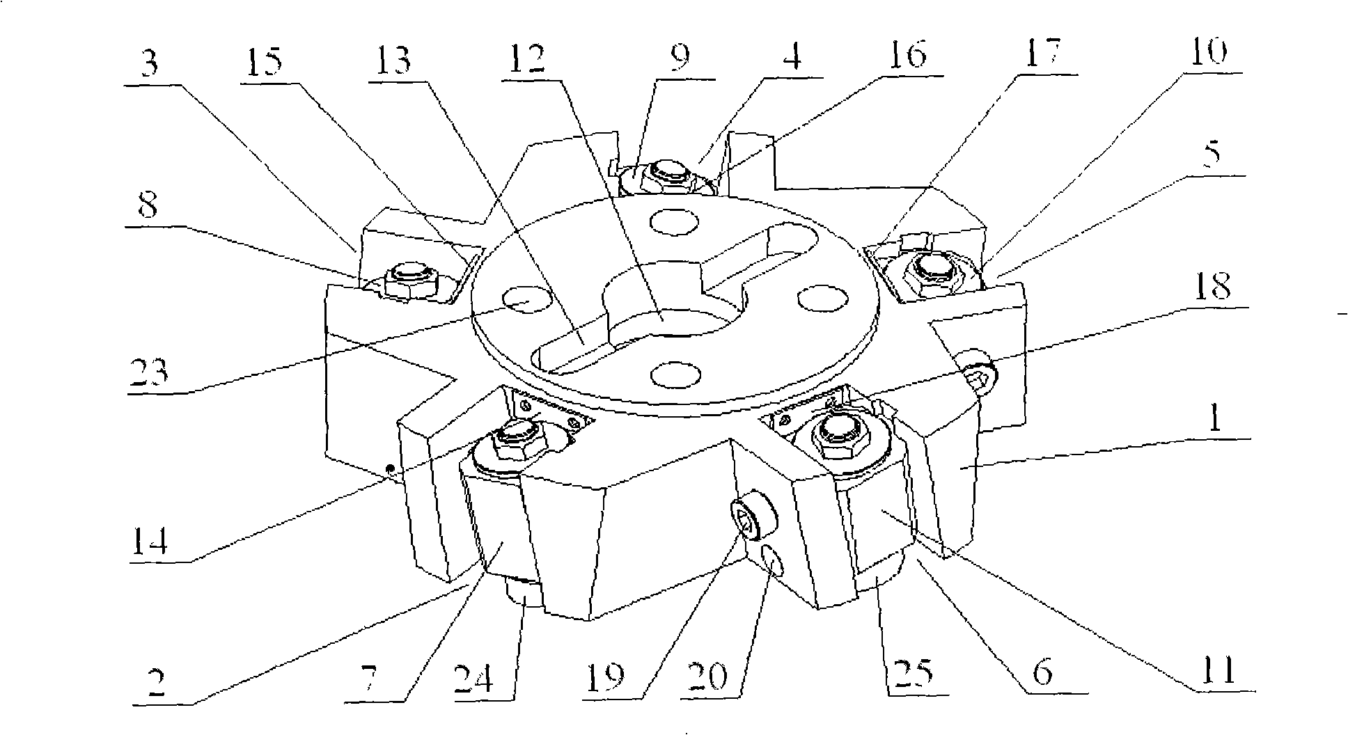
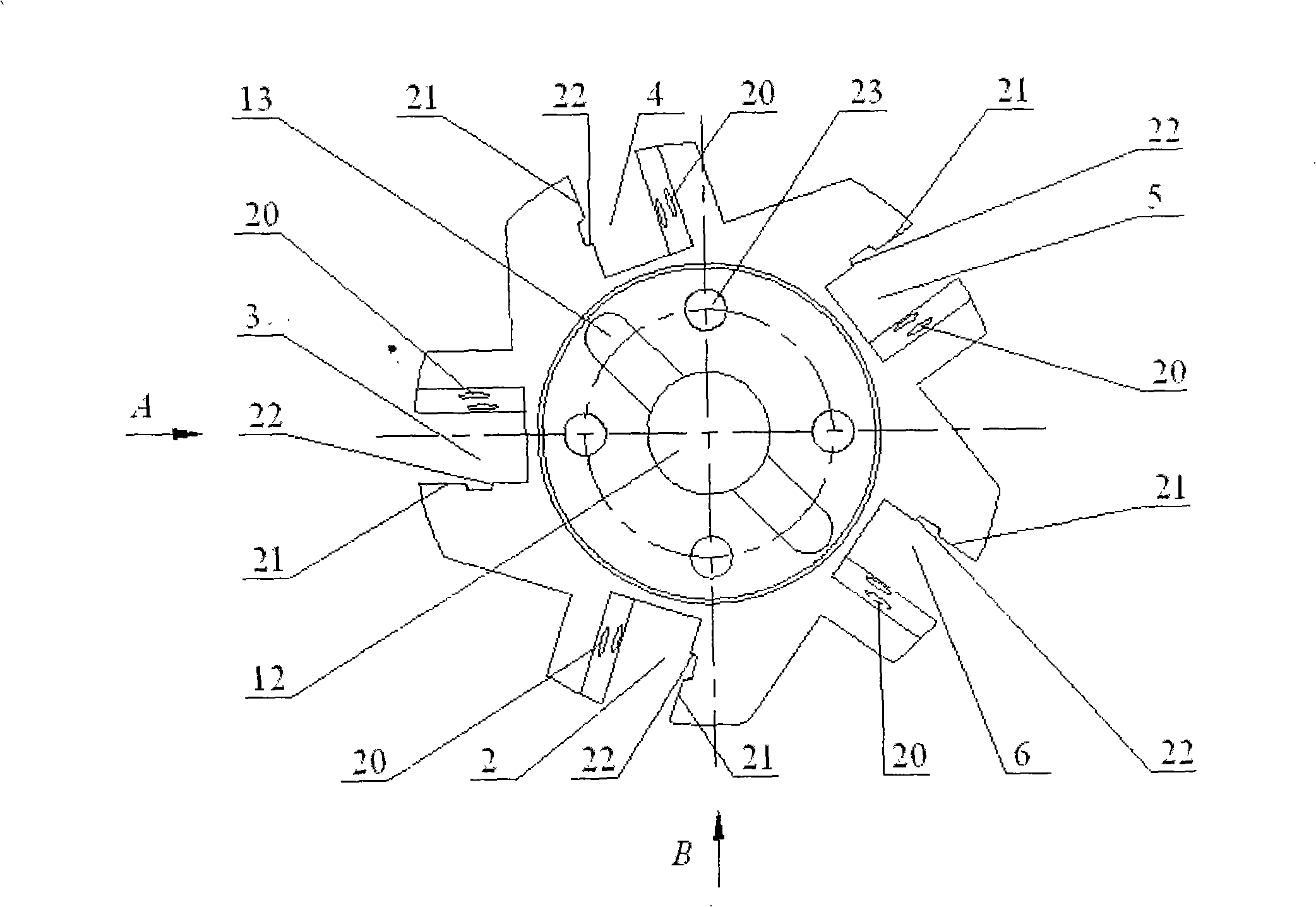
[0039] figure 1 , 2 , 3, 4, 5, and 6 are the structural diagrams of the cutter body and the tool seat groove. The cutter body 1 is an odd number and five-groove structure, and the cutting tool seat 7, 8, 9, 10, install the trimming knife seat 11 in the knife seat groove 6.

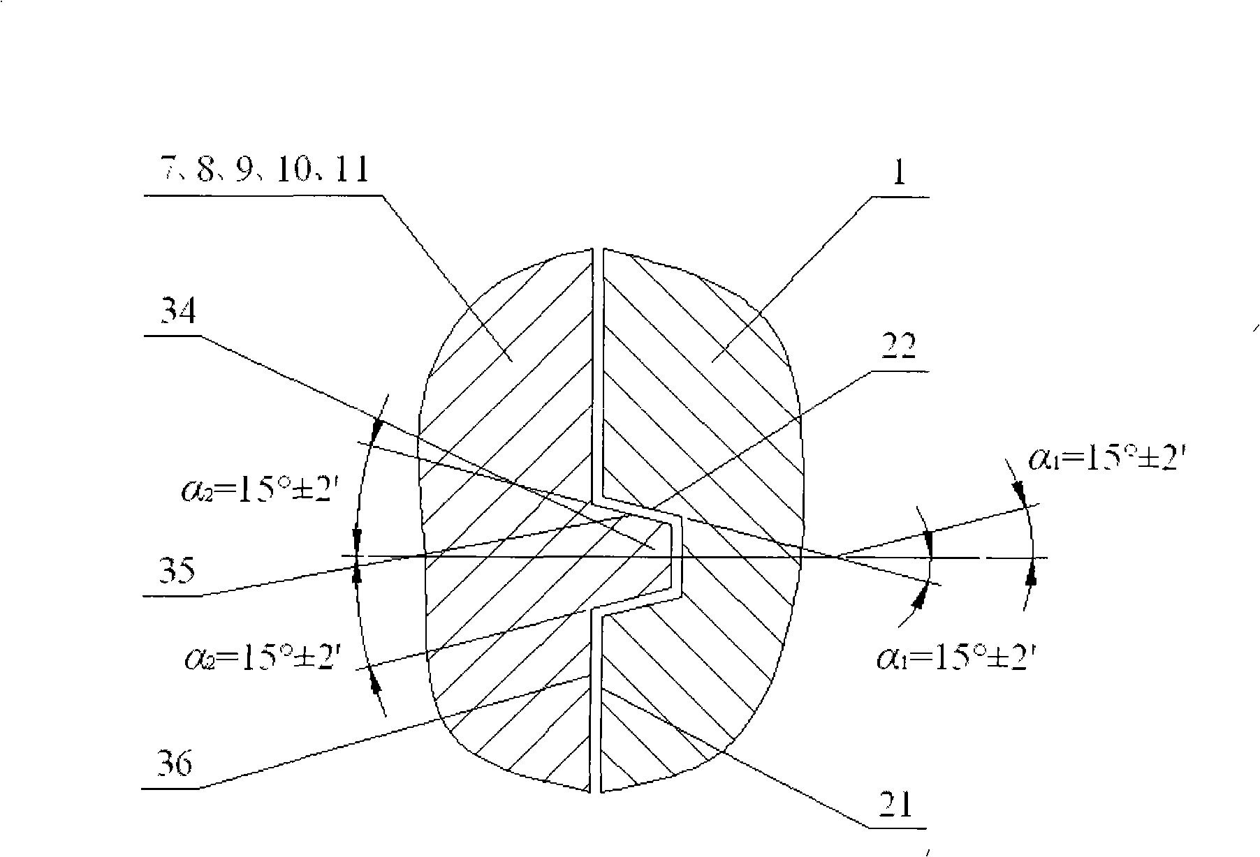
[0040]Knife seat grooves 2, 3, 4, 5, 6 have the same structure and are interchangeable. The corresponding surfaces match, the plane positioning surface 21, the taper positioning surface 22 are consistent with the plane positioning surface 36 and the taper positioning surface 35 on the tool holder in size and angle, and are precisely manufactured to form reliable over-positioning. The taper positioning surface 22 and the taper positioning surface The taper angles of the positioning surfaces 35 are all 15°±2′.

[0041] Knife body 1 is to install knife seat, blade position, bears impact force big, want...


PUM


Abstract

The invention discloses a self-propelled rotary face milling cutter with a slicking blade, comprising a cutter body, a tool apron slot, a cutting tool apron, a slicking tool apron, a positioning surface, a bearing, a cutting blade and a slicking blade. The cutter body is in an odd-number five-slot shape. The tool apron comprises the cutting tool apron and the slicking tool apron. The cutting tool apron utilizes a cutter shaft supporting structure of combining the angular contact bearing and the composite bearing. The slicking tool apron utilizes a cutter supporting structure of combing enclasping up-and-down sliding bearing ring and the composite bearing. The tool apron slot utilizes an over-positioning structure of repeated limiting of the conical surface and the planar surface, and the tool apron slot inclines in both axial direction and the radial direction, so as to enable the self-rotary blade to obtain the cutting edge inclination angle and ensure the continuous self-rotation during processing. The blade utilizes a tangential structure. The slicking blade finally finishes processing the surface. The milling cutter has the advantages of reasonable design, compact structure, good cutting performance, fast cutting speed and high processing precision. The milling cutter also has the advantages that the cutting speed is increased by 50%, the processing precision is improved by 1-2 levels, the surface roughness is up to Ra0.8 micrometers, cooling lubricant is replaced by drying milling, environmental pollution is avoided, and the cutting and slicking functions complement with each other.

Description

technical field [0001] The invention relates to a self-rolling plane milling cutter with a wiper blade, which belongs to the technical field of mechanical processing cutters. Background technique [0002] In mechanical processing, metal cutting tools are very important. In aerospace, aviation and military industries, there are more and more difficult-to-machine materials, and the requirements for metal cutting tools are getting higher and higher. Due to the high cutting temperature and fast tool wear, Frequent use of cooling lubricating fluid not only increases the cost, but also brings pollution. [0003] Among cutting tools, milling cutters are one of the most commonly used machining tools, especially end face and plane milling tools are more common. Due to the large amount of plane milling of mechanical parts, the consumption of tools is very large and the milling speed is low. , The poor quality of milling prompts people to improve the structure of milling tools, but th...

Claims


Application Information

Patent Timeline
IPC IPC(8): B23C5/06B23C5/20
Inventor 庞学慧张晓艳
Owner ZHONGBEI UNIV
Why Eureka
Try Eureka