
SOG structure micro heat pipe and its manufacture method

A micro heat pipe and silicon wafer technology, applied in indirect heat exchangers, lighting and heating equipment, etc., can solve problems such as limited heat transfer capacity, improve heat pipe performance, increase capillary driving force, improve performance and maximize heat transfer effect of ability

Inactive Publication Date: 2008-09-17
HARBIN INST OF TECH
View PDF0 Cites 7 Cited by
  • Summary
  • Abstract
  • Description
  • Claims
  • Application Information

AI Technical Summary

Problems solved by technology

This array structure is equivalent to placing multiple single-groove micro heat pipes on a flat plate, which improves the maximum heat transfer capacity of the heat pipe to a certain extent. is also extremely limited

Method used


Image

  • SOG structure micro heat pipe and its manufacture method
  • SOG structure micro heat pipe and its manufacture method
  • SOG structure micro heat pipe and its manufacture method

Examples


Embodiment Construction

[0033] The present invention is described in more detail below in conjunction with accompanying drawing example:

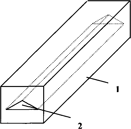
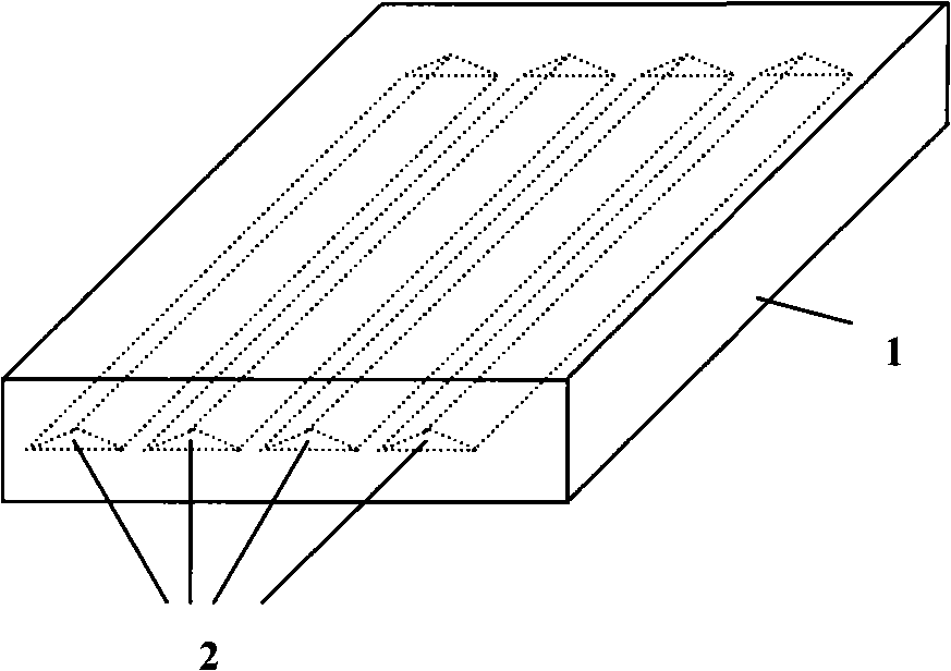
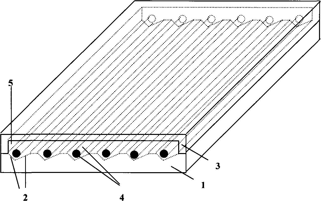
[0034] In the figure 1. Silicon wafer substrate; 2. Working fluid return groove; 3. Glass cover sheet; 4. Glass filament; 5. Connected steam chamber; 6. Liquid injection hole; 7. CPU; 8. SOG micro heat pipe; 9. Heat dissipation aluminum plate. combine image 3 , the composition of the SOG micro heat pipe in this embodiment includes three main parts: a silicon wafer substrate, a glass wafer and a glass filament; at the same time in conjunction with Figure 5, a series of parallel triangular grooves are etched on the substrate silicon wafer by anisotropic etching 2. The sharp corner area of ​​the groove can provide capillary force for the backflow of the working fluid, and it is also a channel for the backflow of the working fluid. Put a straight glass filament in the groove 3. The existence of the glass filament can reduce the meniscus of the gas-liquid interface. ...


PUM


Abstract

The invention provides a SOG(Silicon on Glass)micro heat pipe and the production method. Wherein, the structure uses a silicon chip as substrate, uses synthetic glass as cover film, and the two are sealed together to form enclosed construction through electrostatic bonding, then the liquid-filled is carried out through a pinhole set aside on the silicon chip, and the liquid-filled hole is vacuum-sealed to form a micro flat structure heat pipe whose cavity is filled with certain working fluid. Due to a glass silk, which not only can reduce radius of the meniskus at the gas-solution interface, but also can increase the number of cusp district in a groove, thus improves capillary force for the circumfluence of working fluid. The cover film uses glass sheet, thus enhances visibility so as to carry out real-time observation and monitoring for the functional mode of micro heat pipe. The invention also uses a rectangular cavity etched on the glass as the circulation space of saturated vapor. The connected vapor circulation space can reduce shear friction caused by the high-speed reverse movement of vapor flow and liquid flow at the steam-liquid interface, thus improves the entrainment limit of heat pipe, which ultimately increases the maximum heat output.

Description

(1) Technical field [0001] The invention relates to a novel silicon-based miniature multi-channel flat heat pipe radiator, in particular to the manufacture of a SOG structure micro heat pipe using glass filaments as auxiliary liquid-absorbing cores. (2) Background technology [0002] Traditional cooling technologies, such as forced convection cooling with fans combined with heat sinks, and semiconductor thermoelectric cooling, have been unable to meet the heat dissipation requirements of today's integrated circuits due to constraints such as heat transfer capabilities or processing costs. Heat pipe technology is a technology that does not require an external drive and only relies on its own heat absorption as power to dissipate heat. It has been widely and maturely applied in large-scale heat dissipation. With the development and progress of MEMS technology and microfabrication technology, Micro heat pipe (MHP) cooling technology has become one of the most attractive heat di...

Claims


Application Information

Patent Timeline
IPC IPC(8): F28D15/02
Inventor 刘晓为霍明学王超王喜莲徐磊
Owner HARBIN INST OF TECH
Learn More