
Engine oil processing system

An engine oil and processing system technology, applied to engine components, machines/engines, engine lubrication, etc., can solve the problems of difficult to accurately control the fuel injection angle, reduce the oil life cycle, increase engine wear and other problems, and improve fuel utilization. rate, increase engine life, increase the effect of service life

Active Publication Date: 2008-09-24
CHERY AUTOMOBILE CO LTD
View PDF0 Cites 14 Cited by
  • Summary
  • Abstract
  • Description
  • Claims
  • Application Information

AI Technical Summary

Problems solved by technology

However, it is difficult to accurately control the fuel injection angle, and it is also difficult to grasp the airflow direction in the combustion chamber under different speeds and loads. The oil dilution problem cannot be completely solved, and there is still a serious oil dilution phenomenon, which seriously reduces the service life of the engine oil and increases Engine wear, reducing engine life

Method used


Image

  • Engine oil processing system
  • Engine oil processing system
  • Engine oil processing system

Examples


Embodiment Construction

[0020] Below in conjunction with accompanying drawing, the present invention is done further explanation:

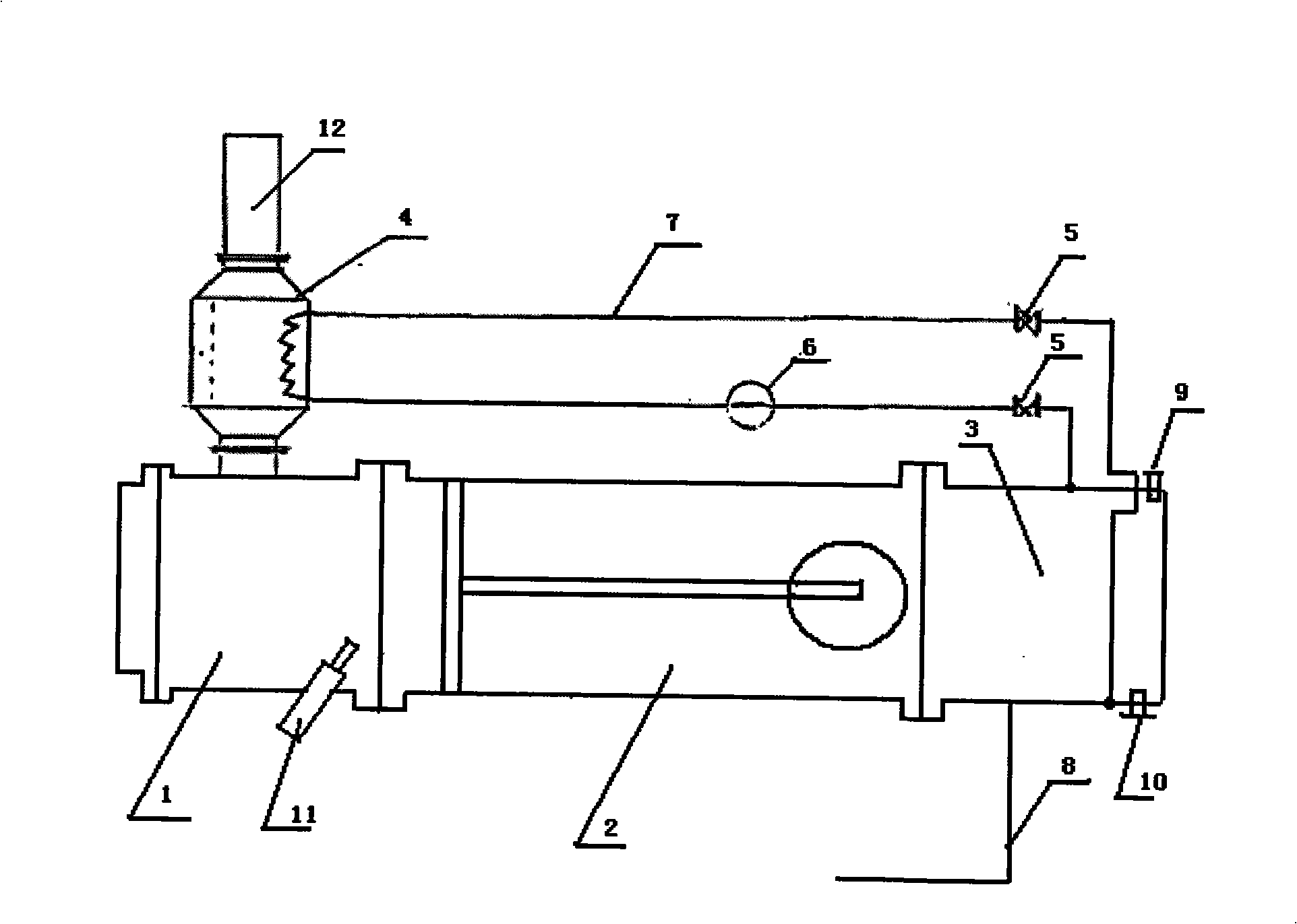
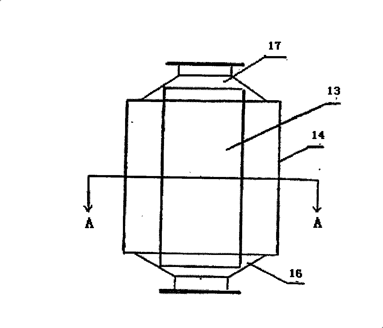
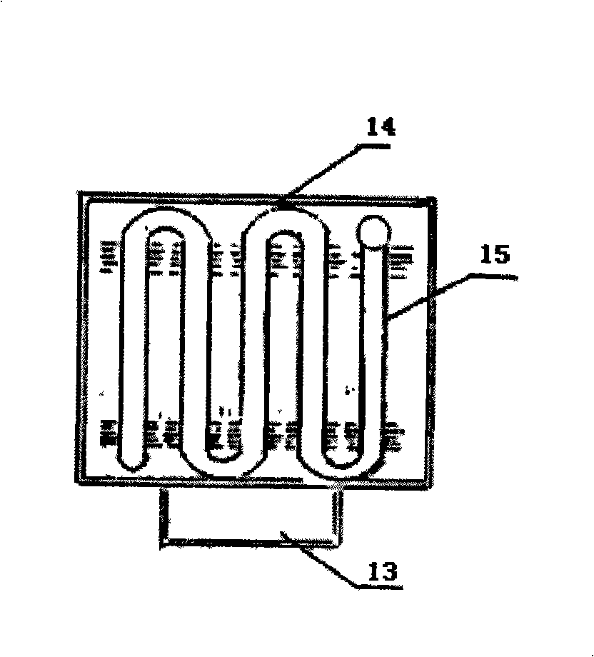
[0021] When the oil pressure sensor detects that the oil pressure is lower than a certain value, under the control of the ECU, the oil circuit switch valve 5 is opened, the oil pump 6 starts to work, and the heat preservation oil circuit oil starts to flow under the action of the oil pump. The oil first enters the heat exchanger. The heat exchanger is composed of an adjustable damper 13, a housing 14, a coil pipe 15, and smoke inlets and outlets 16, 17. The adjustable damper 13 can adjust the exhaust resistance and control the temperature rise. Coil 15 is to increase the oil and exhaust contact area. After the high-temperature exhaust gas enters the heat exchanger through the smoke inlet 14, the oil in the coil pipe 15 is heated, and the temperature of the machine oil rises through the heat exchange of the coil pipe. The heated engine oil enters the oil pan and the in...


PUM


Abstract

The invention relates to a processing system aiming at the dilution problem of engine oil. The processing system comprises a heat exchanger, the engine oil, an insulating tube, an oil pump, an oil pressure sensor, an oil temperature sensor, an oil way switch and a vent pipe used for recycling fuel. When the engine is in operation, if oil pressure valve is below limiting value, an exhaust manifold is used to heat the insulating tube. The engine oil of a control pipeline and the fuel in an oil sump are used to exchange heat to lead bulk temperature to the boiling point of the fuel, thus separating the fuel from lubricant. The separated fuel goes through ventilation system and enters burning system again.

Description

technical field [0001] The invention relates to a treatment system for engine oil dilution, in particular to a treatment system for in-cylinder direct injection engine oil dilution. Background technique [0002] For in-cylinder direct injection engines, the fuel is directly injected into the cylinder. At present, the injection angle and penetration distance of the fuel in the combustion chamber and the direction of the air flow in the cylinder are usually controlled in the world to prevent the fuel from hitting the wall and solve the dilution of the fuel from seeping into the crankcase through the piston ring. Oil problem. However, it is difficult to accurately control the fuel injection angle, and it is also difficult to grasp the airflow direction in the combustion chamber under different speeds and loads. The problem of oil dilution cannot be completely solved, and there is still a serious oil dilution phenomenon, which seriously reduces the service life of the engine oil...

Claims


Application Information

Patent Timeline
IPC IPC(8): F01M5/00
Inventor 王伟
Owner CHERY AUTOMOBILE CO LTD
Learn More