
Testing device for influence of atmospheric turbulence to spacing laser communication

A technology of laser communication and atmospheric turbulence, applied in transmission monitoring/testing/fault measurement systems, electrical components, electromagnetic wave transmission systems, etc. Problems such as not establishing a complete mathematical model to achieve the effect of improving accuracy

Inactive Publication Date: 2008-09-24
CHANGCHUN UNIV OF SCI & TECH
View PDF1 Cites 19 Cited by
  • Summary
  • Abstract
  • Description
  • Claims
  • Application Information

AI Technical Summary

Problems solved by technology

However, due to the influence of atmospheric turbulence, when the laser transmits in the turbulent atmosphere, the coherence degradation, phase fluctuation, arrival angle fluctuation, light intensity fluctuation and other factors of the light wave will cause the tracking of the beam acquisition, alignment and tracking subsystem of the laser communication system. Accuracy, communication rate and bandwidth, bit error rate, etc. will all have an impact
In fact, the influence of the atmosphere on the laser communication system also includes the influence of atmospheric molecules such as absorption and scattering. There have been clear mathematical models to describe and analyze the influence of molecules such as absorption and scattering. The description of the mathematical model is not perfect, so the influence of turbulence on the laser communication system has not established a complete mathematical model so far. The analysis methods are all carried out through experiments, and the experimental system is a single verification atmosphere. (Ma Xiaoshan, Zhu Wenyue, Rao Ruizhong, Large aperture laser scintillation instrument and method for measuring atmospheric refractive index structure constant, patent application number: 200710024298.X)

Method used


Image

  • Testing device for influence of atmospheric turbulence to spacing laser communication
  • Testing device for influence of atmospheric turbulence to spacing laser communication
  • Testing device for influence of atmospheric turbulence to spacing laser communication

Examples


Embodiment 1

[0029]The cassette system used in Example 1: The receiving aperture is 20mm~250mm (adjustable), the photodetector uses pin photodiode BPW34B, the CCD uses TCB230, the laser uses a high-power laser with a wavelength of 532nm, and the splitting ratio of the beam splitting prism is 1:1 and depolarized.

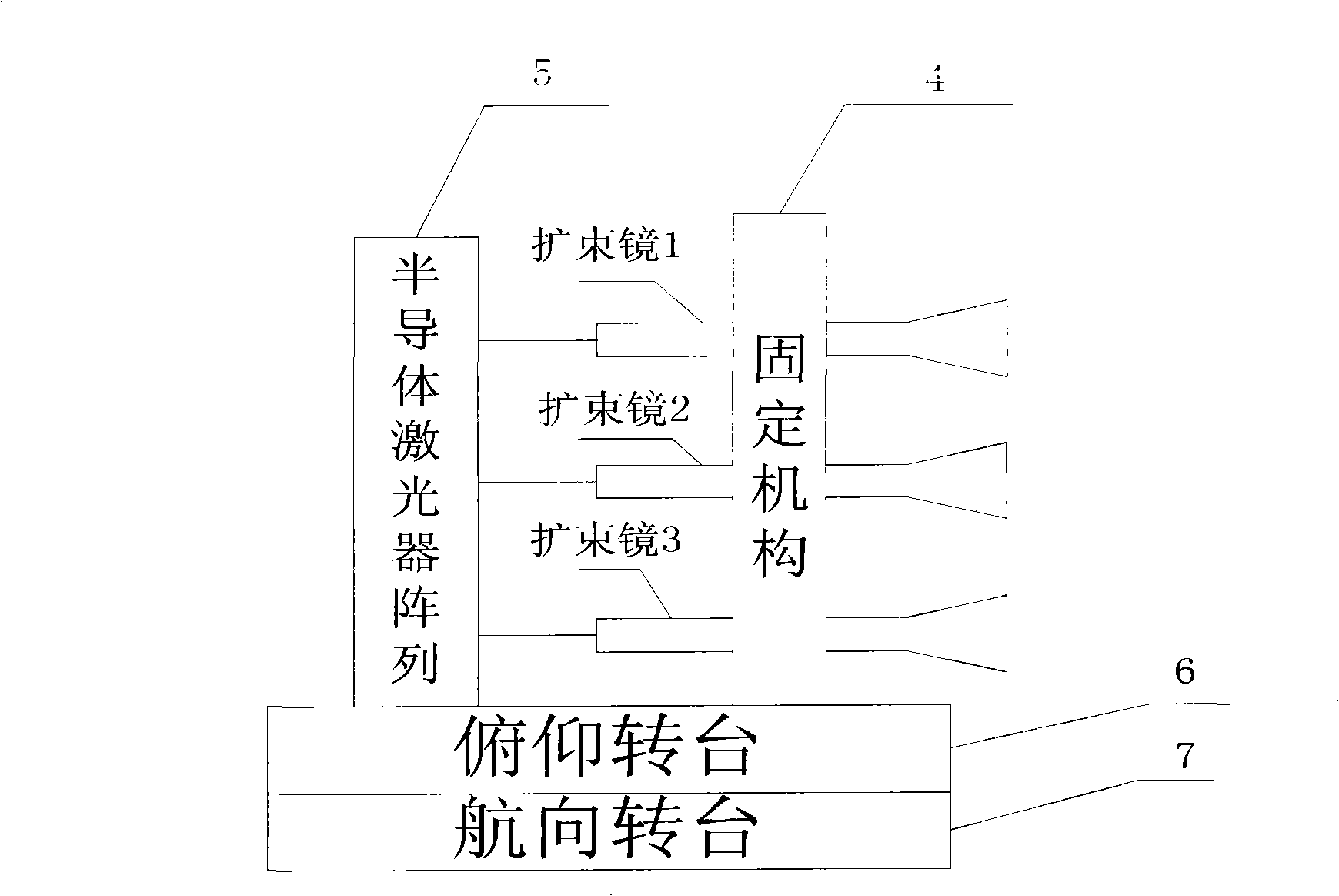
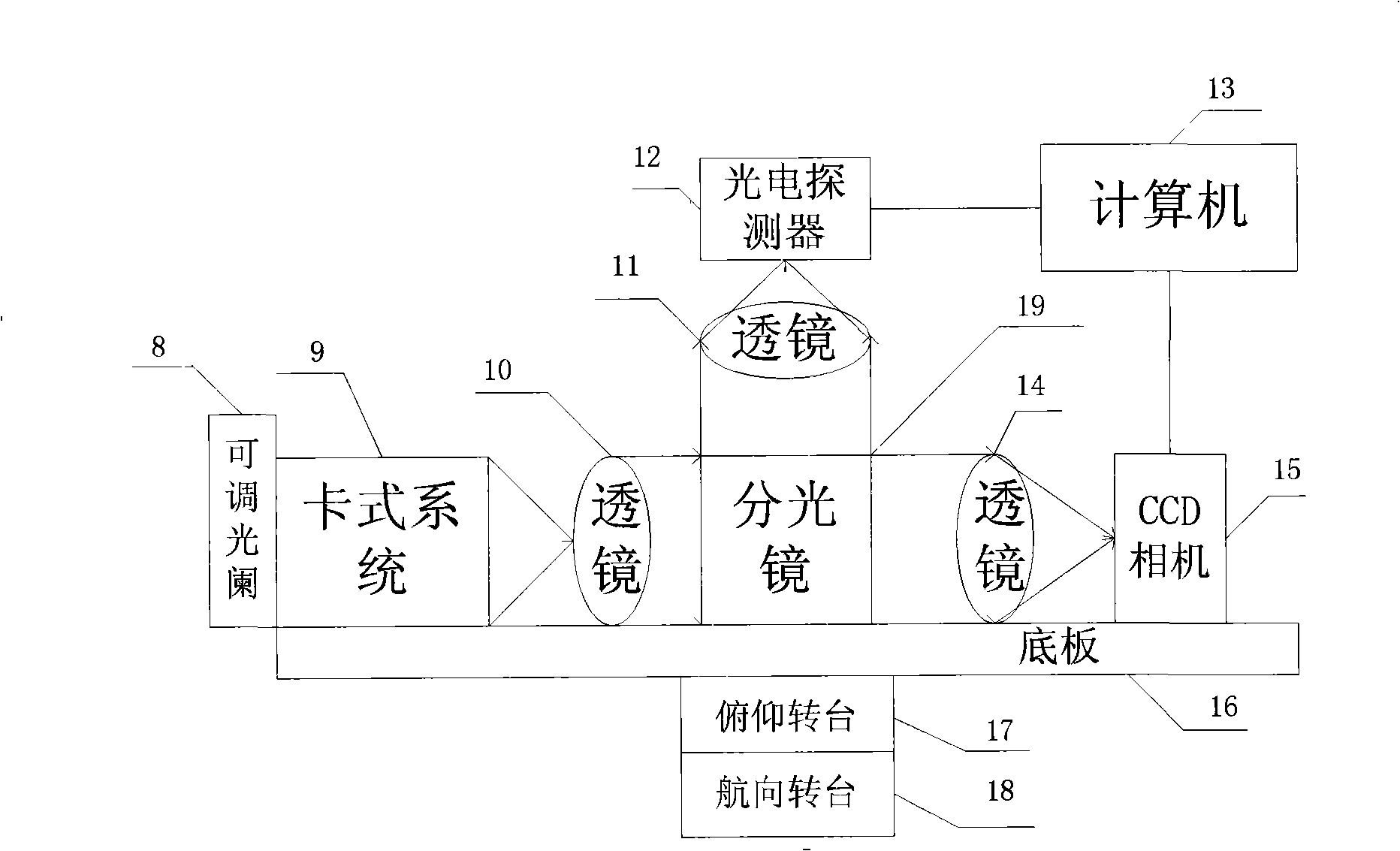
[0030] This Fangming device consists of two parts: a transmitting terminal and a receiving terminal, such as figure 1 with figure 2 Shown.

[0031] Such as figure 1 As shown, the transmitting terminal is composed of a beam expander 1, a beam expander 2, a beam expander 3, a fixing mechanism 4, a semiconductor laser array 5, a pitch turntable 6, and a heading turntable 7;

[0032] The beam expander 1, the beam expander 2, and the beam expander 3 are fixed on the fixing mechanism 4, and the relative position between them can be adjusted; the beam expander 1, the beam expander 2, and the beam expander 3 They are respectively connected with the semiconductor laser array 5 through optic...


PUM

PropertyMeasurementUnit
Wavelengthaaaaaaaaaa

Abstract

A device for detecting the effects of an atmospheric turbulence to space laser communication provided by the invention consists of an emitting terminal and a receiving terminal; the emitting terminal consists of a laser expanding lens (1), a laser expanding lens (2), a laser expanding lens (3), a fixing mechanism (4), a semiconductor laser array (5), a pitch rotating floor (6) and a course rotating floor (7); the receiving terminal consists of an adjustable diaphragm (8), a card type system (9), a lens (10), a lens (11), a photodetector (12), a computer (13), a lens (14), a CCD camera (16), a pitch rotating floor (17), a course rotating floor (18) and a dispersion prism(19). The detecting device can realize the detecting of the effects of the atmospheric turbulence to space laser communication, can measure an atmospheric refraction index constant, can validate different receiving calibers and different CCD integral times as well as an atmospheric twinkling variance during multi-caliber emitting and can give the time domain and space domain distribution situations of light intensity.

Description

Technical field [0001] The invention relates to a testing device for the influence of atmospheric turbulence on a space laser communication system, and belongs to the technical field of space laser communication. technical background [0002] The laser communication system uses laser as the information carrier. The high coherence and spatial orientation of laser determine the advantages of space laser communication compared with RF communication in many aspects: strong anti-interference ability, good safety, small size and light weight. , Unregulated spectrum, low power consumption, strong system mobility, low cost, transparent transmission protocol, etc. However, due to the influence of atmospheric turbulence, when the laser is transmitted in the turbulent atmosphere, the coherence of the light wave is degraded, phase fluctuations, reach angle fluctuations, light intensity fluctuations and other factors, which will track the beam capture, alignment and tracking sub-systems of th...

Claims


Application Information

Patent Timeline
IPC IPC(8): H04B10/08H04B17/00H04B10/07
Inventor 佟首峰赵馨陈纯毅姜会林
Owner CHANGCHUN UNIV OF SCI & TECH
Learn More