Ion beam emission source for outputting single ionic energy

An ion energy and emission source technology, applied in ion implantation plating, sputtering plating, vacuum evaporation plating, etc., can solve the problems of difficulty in achieving ion beam repeatability, large influence on film quality, etc., and reduce diversity factors. Effects of interference, wide energy adjustment range, and simple manufacturing process

Inactive Publication Date: 2008-10-15
XIAN TECHNOLOGICAL UNIV
View PDF0 Cites 13 Cited by
  • Summary
  • Abstract
  • Description
  • Claims
  • Application Information

AI Technical Summary

Problems solved by technology

[0008] The purpose of the present invention is to provide an ion beam emission source capable of emitting a single energy, so as to overcome the problems in the prior art that the extracted ions do not have a single energy, which has a great impact on the quality of the film, and it is difficult to achieve the repeatability of ion beam assistance.

Method used


Image

  • Ion beam emission source for outputting single ionic energy
  • Ion beam emission source for outputting single ionic energy
  • Ion beam emission source for outputting single ionic energy

Examples


Embodiment 1

[0050] In the preparation of optical thin films, it is usually necessary to use ion beam assisted deposition to improve the film quality of the thin film. The study found that different thin film materials require different ion beam energies to assist. When preparing the ZnS thin film, the ion beam energy required for assisting is 800eV. If the energy is too low, the best assisting effect cannot be obtained, and if the energy is too high, the formed thin film will be sputtered off. Therefore, to adopt the novel ion beam emission source of the present invention, first set the output energy of the ion source to 800eV. During normal operation, the system will automatically adjust the discharge parameters of the ion source to obtain the required output energy value, and adjust to obtain the strongest The ion beam density output. At this time, the energy of the output ions is 800eV.

Embodiment 2

[0052] In the preparation of optical thin films, it is usually necessary to use ion beam assisted deposition to reduce the film forming temperature. Especially when preparing multi-layer thin films, multiple materials are deposited alternately, each material requires different ion beam auxiliary energy, and requires a single energy output. Such as ZnS / MgF 2 When preparing dielectric high-reflection films, ZnS films require an auxiliary ion beam energy of 800eV, while MgF 2 The auxiliary ion beam energy required by the thin film is 1100eV, and both require a single energy output. Therefore, using the novel ion beam emission source of the present invention, the output energies of the ion sources are respectively set to 800eV and 1100eV, and communicate with the host computer. The entire ion source system will automatically adjust the discharge parameters of the ion source according to the actual plated film to obtain the required energy value, and adjust to obtain the stronges...


PUM


Abstract

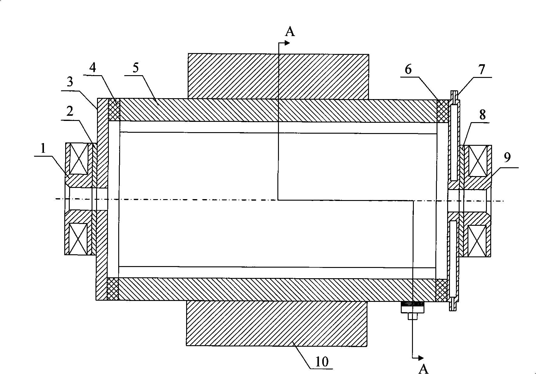
The invention relates to an ion beam emission source capable of outputting single iron energy so as to solve the problems of the prior art that the extracted ion does not have single energy, the quality of the film is greatly influenced and the repeatability of ion beam assistance is difficult to realize. The technical proposal is as follows: the emission source comprises a gas discharge chamber, a focusing magnetic field generating unit, an ion energy selector and a beam expanding magnetic field generating unit; the gas discharge chamber comprises an anode, a cathode and an extracting grid plate; the ion energy selector comprises an upper magnetic polar plate and a lower magnetic polar plate which are oppositely arranged, and a selecting cylinder which is formed by a first electrode plate and a second electrode plate which are oppositely arranged; polar plate insulating members are arranged among the upper magnetic polar plate, the first electrode plate, the lower magnetic polar plate and the second electrode plate; and the centers of an inlet cover plate and an outlet cover plate at two ends of the selecting cylinder are respectively provided with an energy band limit through hole. Compared with the prior art, the emission source has the advantages that: 1. ion with single energy can be generated and extracted; 2. the energy of the ion is adjustable; and 3. the manufacture process is simple.

Description

Technical field: [0001] The invention relates to an ion beam emitting source (ion source) device used in an optical vacuum ion beam assisted coating machine or ion beam etching equipment, in particular to an ion beam emitting source capable of outputting single ion energy. Background technique: [0002] In the field of thin film technology, ion beam assist (IBAD) is an optical surface coating technology that combines thin film deposition (mainly physical vapor deposition) with ion bombardment, usually in a high vacuum evaporation chamber using an ion source. The energetic ion beam bombards the substrate material being deposited into the thin film, so as to obtain a certain effect of the thin film. Generally speaking, ion beam assisted coating technology overcomes the respective shortcomings of physical vapor deposition and ion bombardment, so it is quite distinctive. This technology can improve the performance of the film and achieve the effect that cannot be obtained by th...

Claims


Application Information

Patent Timeline
IPC IPC(8): C23C14/24H01L21/3065C23F4/00H01J37/08
Inventor 徐均琪杭凌侠弥谦苏俊宏朱昌严一心
Owner XIAN TECHNOLOGICAL UNIV
Why Eureka
Try Eureka