Rotary cylindrical magnetron sputtering target

A magnetron sputtering and cylindrical target technology, applied in the field of thin film preparation, can solve the problems of low ionization rate of argon gas and low sputtering rate, etc., achieve uniform etching, high surface quality of film layer, economic and social benefits significant effect

Inactive Publication Date: 2008-10-15
SUPERIOR COAT SUZHOUCO
View PDF3 Cites 17 Cited by
  • Summary
  • Abstract
  • Description
  • Claims
  • Application Information

AI Technical Summary

Problems solved by technology

The ionization rate of argon gas is very low due to the short

Method used


Image

  • Rotary cylindrical magnetron sputtering target
  • Rotary cylindrical magnetron sputtering target
  • Rotary cylindrical magnetron sputtering target

Examples


Embodiment Construction

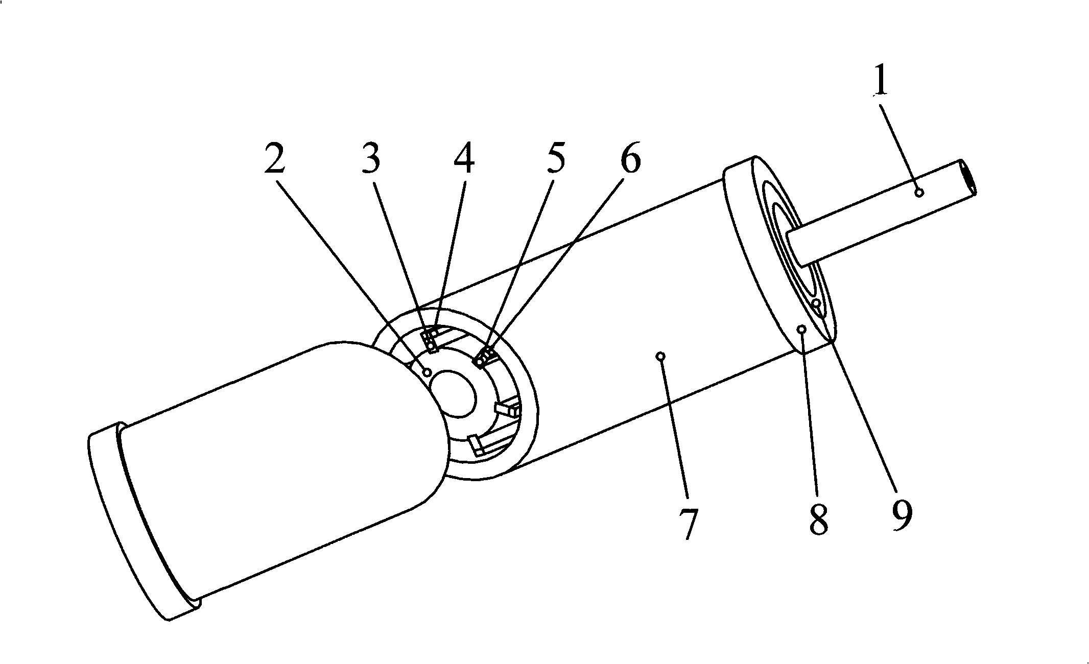
[0023] In addition to an electric field applied on the target by magnetron sputtering coating (the electric force line is perpendicular to the target surface), a magnetic field is also applied to make the electrons be affected by the Lorentz force and make cycloidal and helical composite motions to extend the electron trajectory. , so that the plasma density is greatly increased, and the number of positive ions is also greatly increased, which can increase the sputtering rate.

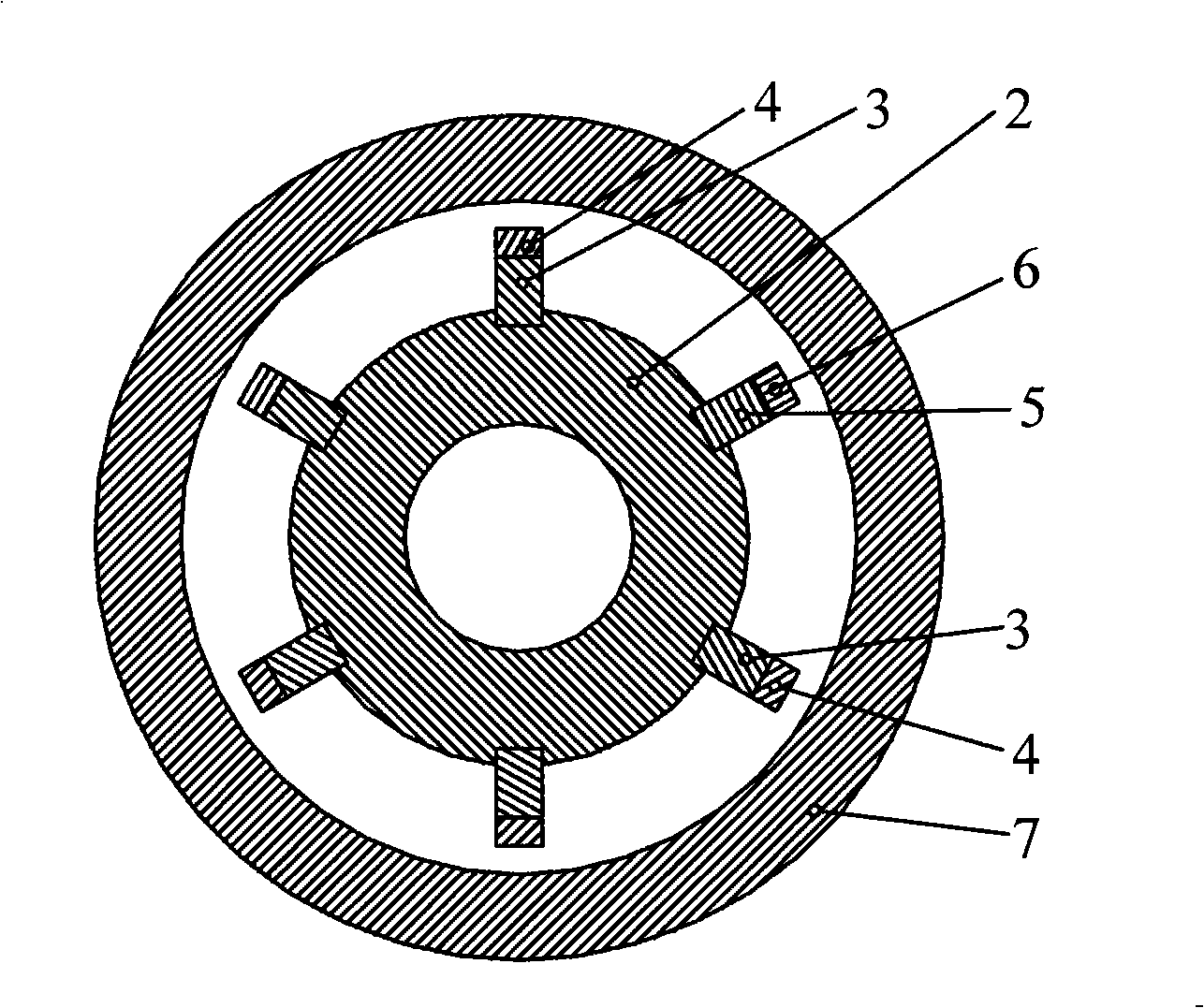
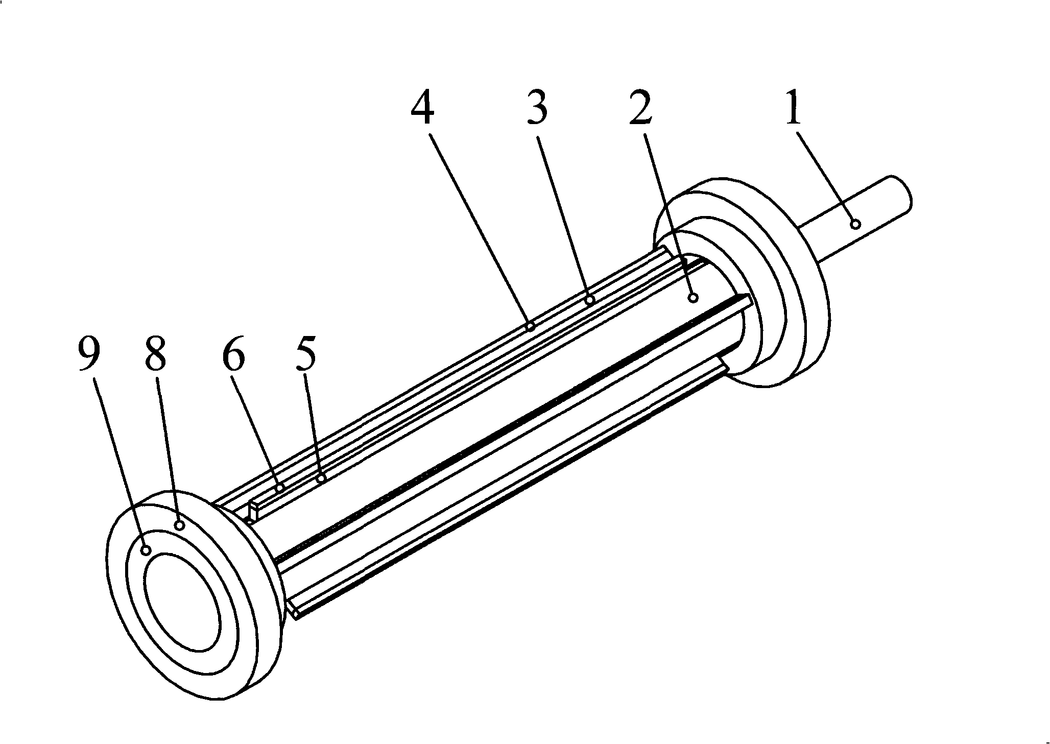
[0024] Such as figure 1 As shown in ~4, the rotary magnetron sputtering central column target includes pole piece 2, permanent magnets 3 and 5, layering bars 4 and 6, hollow cylindrical target material 7 and rotating mandrel 1, and permanent magnet 3 is a long permanent magnetic strip. The permanent magnet 5 is a short permanent magnetic strip. Correspondingly, the pole shoe 2 is provided with positioning grooves for installing the long permanent magnetic strip 3 and the short permanent magnetic strip ...


PUM


Abstract

The invention provides a rotary cylindrical magnetic control sputtering target, which comprises a pole terminal, permanent magnets, hollow cylindrical target material and a mandrel, wherein, the permanent magnets are embedded into the pole terminal along the axial direction of the cylindrical target material; the permanent magnets are long permanent magnetic strips and short permanent magnetic strips; positioning slots which are used for arrangement of the long permanent magnetic strips and the short permanent magnetic strips are arranged on the pole terminal; the long permanent magnetic strips and the short permanent magnetic strips are respectively arranged in corresponding positioning slots; a multipath bar magnet is formed by alternate distribution of the long permanent magnetic strips and the short permanent magnetic strips along the circumferential direction of the pole terminal; the polarity of the long permanent magnetic strips and that of the short permanent magnetic strips are different; the polarization direction is perpendicular to a central axis of a sputtering cathode; and closed racetrack shaped magnetic force lines are formed by magnetic rings on both ends of the pole terminal and the long permanent magnetic strips and the short permanent magnetic strips. The rotary cylindrical magnetic control sputtering target realizes low air pressure, high density and uniformity of discharge plasma, guarantees formation of a closed electronic racetrack under the condition of glow discharge, makes sputtering perform stably, has good surface quality of membranous layers and compact membranous layers, and is uniform in the consumption of the target materials and high in the utilization rate of the target materials.

Description

technical field [0001] The invention relates to a rotating cylindrical magnetron sputtering target for large-area coating, which is widely used in coating preparation equipment and belongs to the technical field of thin film preparation. Background technique [0002] At present, the magnetron sputtering equipment at home and abroad mainly has two types of sputtering source targets: coaxial magnetron sputtering target and planar magnetron sputtering target. The material is equipped with ring-shaped permanent magnets and pole shoes (magnetic pads). During sputtering, several ring-shaped glow discharge areas with gaps perpendicular to the target axis are formed. When plating large-area substrates (such as curtain walls) Glass) will inevitably form thick and thin stripes, resulting in serious uneven film thickness and affecting product quality. The planar magnetron sputtering target adopts a bar-shaped magnet structure, and a strip-shaped glow area parallel to the target axis i...

Claims


Application Information

Patent Timeline
IPC IPC(8): C23C14/35
Inventor 孙德恩
Owner SUPERIOR COAT SUZHOUCO
Why Eureka
Try Eureka