Method for detecting aqueduct well by underwater robot

An underwater robot and aqueduct technology, applied in the direction of using optical devices, instruments, measuring devices, etc., can solve the problems of low measurement accuracy, high measurement difficulty, measurement interference from external factors, etc.

Active Publication Date: 2008-10-29
HUADONG TIANHUANGPING PUMPED STORAGE +1
View PDF0 Cites 30 Cited by
  • Summary
  • Abstract
  • Description
  • Claims
  • Application Information

AI Technical Summary

Problems solved by technology

[0003] In order to solve the problems existing in the existing human-made measurement methods, such as the interference of many measurement external factors, the dif...

Method used


Image

  • Method for detecting aqueduct well by underwater robot
  • Method for detecting aqueduct well by underwater robot

Examples


specific Embodiment approach 1

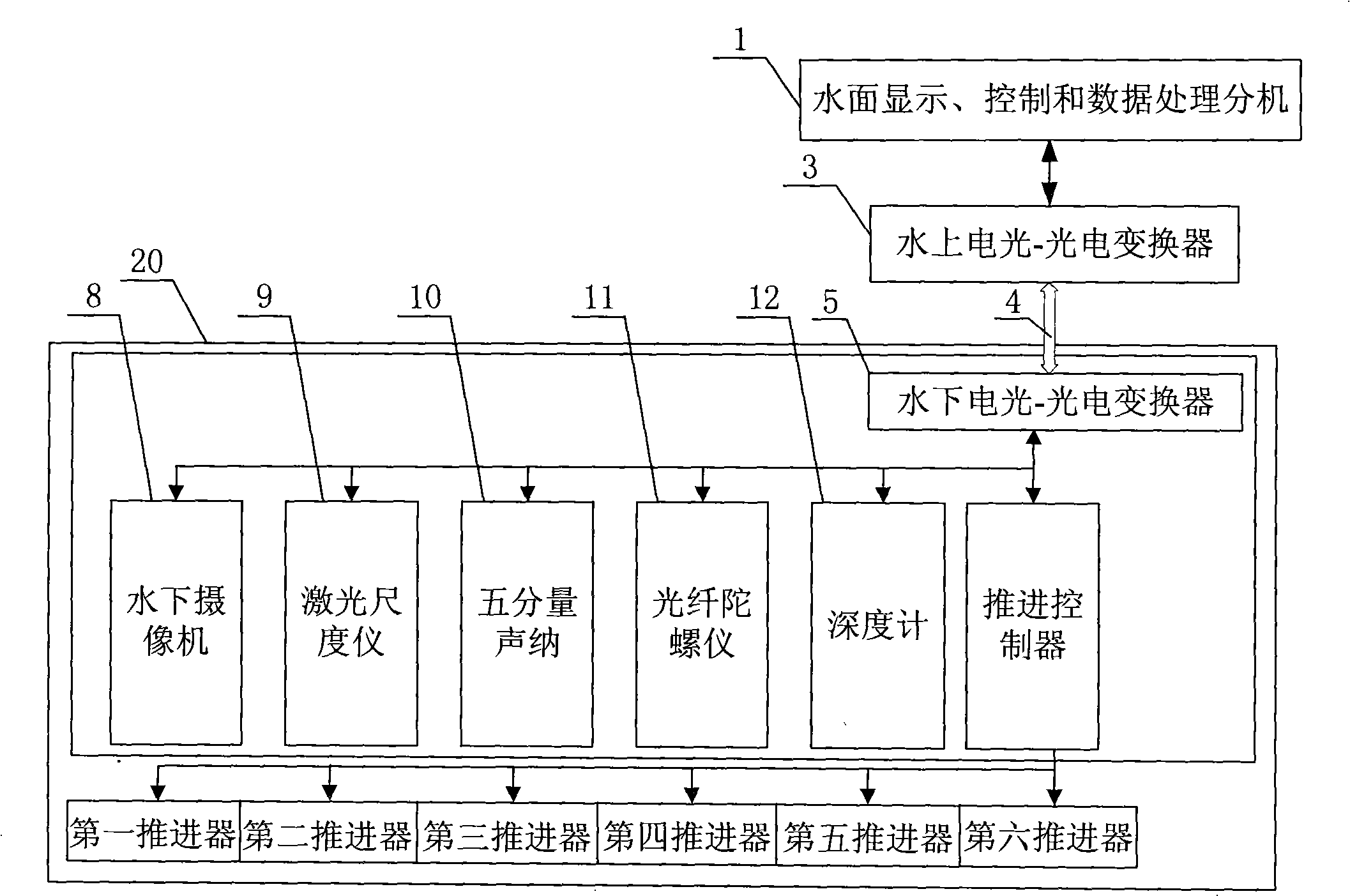
[0012] Specific implementation mode one: combine figure 1 with figure 2 Describe this embodiment, in this embodiment, the underwater robot used for the inspection in the well of the aqueduct consists of a water surface display, control and data processing extension 1, an underwater camera 8, a laser scale 9, a five-component sonar 10, and a fiber optic gyroscope 11 , a depth gauge 12 and an underwater robot body 20;

[0013] The steps of this embodiment are as follows:

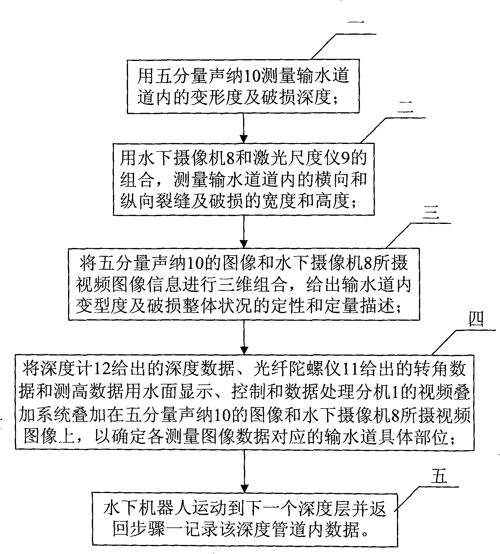
[0014] Step 1: Measure the degree of deformation and damage depth in the water delivery channel with a five-component sonar 10;

[0015] Step 2: measure the width and height of transverse and longitudinal cracks and damage in the aqueduct with a combination of the underwater camera 8 and the laser scaler 9;

[0016] Step 3: Three-dimensionally combine the images of the five-component sonar 10 and the video image information captured by the underwater camera 8 to give qualitative and quantitative descriptio...

specific Embodiment approach 2

[0020] Specific embodiment 2: The difference between this embodiment and specific embodiment 1 is that the five-component sonar 10 in step 1 is based on the principle of underwater acoustic ranging, respectively in four horizontal orthogonal directions and a vertical downward height measurement direction. Measure the data of five points, and with the movement of the robot, the water surface display, control and data processing extension 1 will connect the data of each measurement point transmitted from the underwater in real time into a line to form a circular image, so as to obtain a The deformation degree of the section and the measurement data of the damage depth. Other compositions and connection methods are the same as those in Embodiment 1.

specific Embodiment approach 3

[0021] Specific embodiment 3: The difference between this embodiment and specific embodiment 1 is that the underwater camera 8 in step 2 is driven by the movement of the underwater robot to perform a circular motion along the inner wall of the water delivery pipeline, so that the water delivery pipeline can be filmed Video image of the damage condition at the depth where the underwater robot is located on the inner wall. The parameters obtained for the video image of the damaged state are the length and width data of the damage. Other compositions and connection methods are the same as those in Embodiment 1.


PUM


Abstract

The invention discloses a method for detecting the inside of a waterway well by adopting an underwater robot and relates to a method of detecting the inside of a waterway well. The method solves the problems of the prior method, including too much interference, great difficulty and low accuracy. The method comprises the following steps: (1) measuring the degree of deformation and the depth of breakage by using a five-component sonar; (2) measuring the width and the height of crack and breakage in the transversal and the longitudinal directions by using an underwater camera and a laser scale instrument; (3) combining the images measured by the five-component sonar and the underwater camera, and giving the qualitative and the quantitative description of the degree of deformation and the whole state of breakage; (4) superposing the data given by a depth gauge and a optical fiber gyroscope on the images to determine the specific waterway position corresponding to each measured image data; (5) moving the underwater robot to the next depth and returning to step (1) to record the data of the inside of the waterway in the depth. The underwater robot can detect inclined-well and straight-well waterways within 1000 meter.

Description

technical field [0001] The invention relates to a method for detecting the inside of an aqueduct well. Background technique [0002] The high-pressure waterway is the most important part of the peak-shaving power generation of the pumped storage power station. Usually relying on high mountains, reinforced concrete is used as raw material to build pipeline-type vertical or inclined shafts. Its inner diameter is several meters, and its length is hundreds of meters to thousands of meters. Due to its non-stop pumping storage and high-speed cycle use of water discharge for power generation, and the water pressure that must withstand hundreds of meters of water head when the water is full, the reinforced concrete materials are subject to erosion, high and low pressure cycle extrusion, etc. serious. Because of this, the defects of damage and cracks caused by material aging will expand rapidly until the pipeline collapses. Once this happens, it will bring immeasurable economic l...

Claims


Application Information

Patent Timeline
IPC IPC(8): G01N21/954G01B17/04G01B17/00G01B11/02
Inventor 桑恩方安岩袁连喜周明权吴宏炜张晓峻
Owner HUADONG TIANHUANGPING PUMPED STORAGE
Why Eureka
Try Eureka