

Optical pickup device
An optical pickup device, laser technology, applied in the direction of beam guiding device, optical recording head, recording/reproducing by optical method, etc., to achieve the effects of improving S/N, suppressing complexity, and suppressing cost
- Summary
- Abstract
- Description
- Claims
- Application Information
AI Technical Summary
Problems solved by technology
Method used
Image

Examples
no. 1 approach
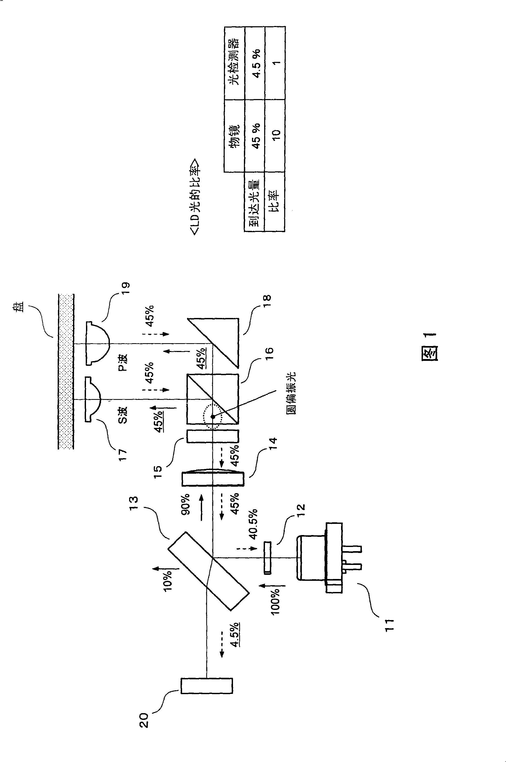
[0036] FIG. 1 shows the configuration (optical system) of an optical pickup device according to the first embodiment. In the figure, 11 is a semiconductor laser (laser light source) that emits blue laser light with a wavelength of about 405 nm; 12 is a diffraction grating that divides the laser light from the semiconductor laser 11 into three beams; 13 is to reflect 90% of the incident laser light and make 10% transmission parallel plate non-polarized light reflector. The non-polarized light reflector 13 is arranged so as to be inclined at a predetermined angle (for example, 45°) with respect to the optical axis of incident laser light.
[0037] 14 is a collimator lens that converts the reflected laser light of the non-polarized light reflector 13 into parallel light; 15 is a 1 / 4 wavelength plate that converts the laser light passing through the collimator lens 14 into circularly polarized light; 16 is a polarization beam splitter .
[0038] 17 is the first objective lens th...
no. 2 approach
[0057] 5A and 5B show the configuration (optical system) of the optical pickup device according to the second embodiment. FIG. 5A is a plan view of the optical system from the semiconductor laser 31 to erected mirrors 36 and 42 , and FIG. 5B is a side view of the optical system after erected mirrors 36 and 22 . In addition, in FIG. 5B, the part of the lens holder 25 is shown in cross-sectional view for convenience.
[0058] In this figure, 31 is a semiconductor laser (laser light source) that emits blue laser light with a wavelength of about 405nm, and 32 is a 1 / 4 wavelength plate 32a and a diffraction grating 32b that convert the laser light from the semiconductor laser 31 into circularly polarized light. After the optical element, 33 is a polarizing beam splitter. Laser light emitted from the semiconductor laser 31 is converted into circularly polarized light by the 1 / 4 wavelength plate 32a. Therefore, 50% (P polarization component) of the laser light incident on polarizat...
no. 3 approach
[0077] This embodiment is a modified example of the first embodiment described above. That is, in the above-mentioned first embodiment ( FIG. 1 ), although the laser light is circularly polarized by a 1 / 4 wavelength plate and enters the polarized beam splitter 16, even if the polarized beam splitter 16 is Adjusting the polarization direction of the laser light in such a manner that the polarization axis is tilted can also achieve the same effect as that of the above-mentioned first embodiment. This embodiment relates to a configuration in which laser light from a semiconductor laser 11 is distributed to first and second objective lenses 17 and 19 by inclining the polarization direction of the laser light relative to the polarization axis of the polarization beam splitter 16 .
[0078] FIG. 6 shows the configuration of the third embodiment. In this embodiment, the 1 / 4 wavelength plate 15 in the first embodiment described above is replaced with a 1 / 2 wavelength plate 21 . Othe...
PUM
 Abstract
Description
Claims
Application Information