Fuel truck nozzle

A refueling gun and fuel technology, applied in special distribution devices, packaging, distribution devices, etc., can solve the problems of limited peak pressure of water hammer and inconspicuous extension time, prolong the closing time, reduce the phenomenon of water hammer, Impact reduction effect

Active Publication Date: 2008-11-05
TOKHEIM HENGSHAN TECH GUANGZHOU
View PDF1 Cites 1 Cited by
  • Summary
  • Abstract
  • Description
  • Claims
  • Application Information

AI Technical Summary

Problems solved by technology

In the pushing process of the spring, the two-stage valve moves down almost without resistance until it is closed. Therefore, the closing time of the control valve of this kind of fuel filler gun with two-stage valve is shorter than that of the control valve of other one-stage valve. Closing time, the extended time is not obvious, and the effect of reducing the peak pressure of water hammer when the fuel nozzle is closed is also very limited

Method used


Image

  • Fuel truck nozzle
  • Fuel truck nozzle
  • Fuel truck nozzle

Examples


Embodiment

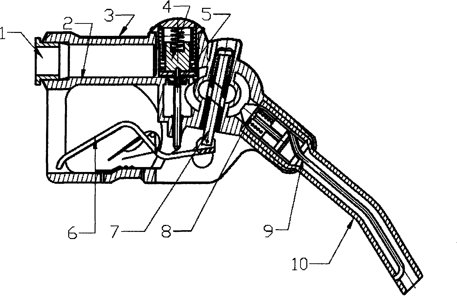
[0026] Such as figure 1 As shown, the fuel oil refueling gun of the present invention is composed of gun body 2, gun body cover 3, control valve 4, oil inlet pipe 1, control handle 6, ejector rod 5, self-control lever 7, vacuum valve 8, oil outlet pipe 10, vent pipe 9 and so on.

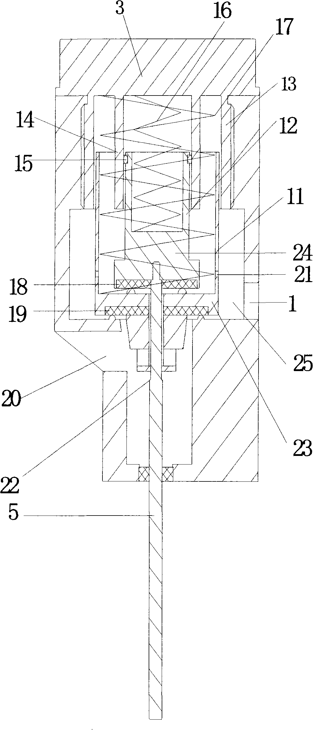
[0027] Such as figure 2 As shown, the gun body cover 3 is fixedly connected with the gun body 2 through threads, and the control valve 4 is arranged on the lower side of the gun body cover 3 and placed between the oil inlet 25 and the oil outlet 20 in the oil inlet pipe 1, and the outlet The oil port 20 communicates with the oil outlet pipe 10, and the control valve 4 includes a main valve and an auxiliary valve located in the main valve and installed concentrically with the main valve; The main valve body 11 and the main valve spring 17 at both ends are respectively offset against the main valve 23 at the bottom of the gun body cover 3 and the main valve body 11; and the auxiliary valve spring 1...


PUM


Abstract

The invention discloses a fuel filling gun which has a control valve; the control valve includes a master valve and a secondary valve arranged inside the master valve; the master valve consists of an external ring that is fixedly arranged under the a gun cover, a master valve body that has clearance fit with the external ring and a master valve spring pack with two ends respectively touches against the gun cover and the bottom of the head valve at the bottom of the master valve body; the secondary valve consists of an internal ring that is fixedly arranged under the gun cover, a secondary valve body and a secondary spring pack with two end respectively touches the gun cover and the secondary valve at the bottom of the secondary valve body. The internal ring has tight fit with the secondary valve by a piston ring; a knockout-pin which is connected with the control handle has a spindle shoulder, the thin segment of the knockout-pin passes through the head valve and the top end is fixedly connected with the secondary valve; the spindle shoulder is limited out of the head valve, and a clearance is left between the head valve and the spindle shoulder when the head valve is closed. The fuel filling gun makes improvement on the control valve, which greatly reduces the water hammer phenomenon, reduces the impact on the hydraulic units of the filling machine when the filling gun is switched on or switched off and improves the performance stability and working reliability of the hydraulic units of the fuel filling machine.

Description

technical field [0001] The invention relates to a fuel filler gun. Background technique [0002] In the hydraulic system of the oil dispenser, due to the drastic change of the fluid flow rate in the pipeline, a series of rapid hydraulic shock phenomena in which the pressure alternately rises and falls is called water hammer. The water hammer occurs because when the liquid flow stops suddenly, due to the action of the flowing liquid and the inertia of the moving parts, its kinetic energy becomes a high-pressure wave starting from the stop point, which is transmitted back and forth along the piping system at a speed close to the speed of sound , causing a high pressure in the system instantaneously. Under normal working conditions, the oil pressure in the fuel dispenser is about 0.1-0.3MPa, but when the fuel dispenser pump starts and stops, and the refueling gun is closed, the experimental results show that the peak value of the water hammer pressure can reach more than 0.7MP...

Claims


Application Information

Patent Timeline
Patent Type & Authority Applications(China)
IPC IPC(8): B67D5/371B67D5/375B67D7/44B67D7/50
Inventor 刘亚俊刘森林蒋征学
Owner TOKHEIM HENGSHAN TECH GUANGZHOU
Why Eureka
Try Eureka