
Light differentiator based on silicon based ring-shaped resonant cavity

A ring resonant cavity and differentiator technology, which is applied in optics, instruments, nonlinear optics, etc., can solve the problems of unsuitable large-scale integration, millimeter level, and large differentiator size, and achieve easy photoelectric integration, easy integration, small size effect

Inactive Publication Date: 2008-11-12
SHANGHAI JIAO TONG UNIV
View PDF0 Cites 23 Cited by
  • Summary
  • Abstract
  • Description
  • Claims
  • Application Information

AI Technical Summary

Problems solved by technology

[0003] Found through literature search to prior art, Naum K.Berger et al. published the article "Temporal differentiation of optical signals using aphase-shifted fiber Bragg grating" in volume 15 of Optics Express in 2006 (light based on phase-shifted fiber Bragg grating time-domain differentiator), this paper utilizes that the reflection spectrum of a fiber Bragg grating with a phase shift of π has similar properties to the spectrum of a differentiator, and can perform accurate and efficient first-order time-domain differentiation of gigabit optical signals, but it is not enough The difference is that the differentiator is large in size, the length is on the order of millimeters, and the material is optical fiber, which is not suitable for large-scale integration

Method used


Image

  • Light differentiator based on silicon based ring-shaped resonant cavity
  • Light differentiator based on silicon based ring-shaped resonant cavity
  • Light differentiator based on silicon based ring-shaped resonant cavity

Examples


Embodiment Construction

[0015] The embodiments of the present invention are described in detail below in conjunction with the accompanying drawings: this embodiment is implemented on the premise of the technical solution of the present invention, and detailed implementation methods and specific operating procedures are provided, but the protection scope of the present invention is not limited to the following the described embodiment.

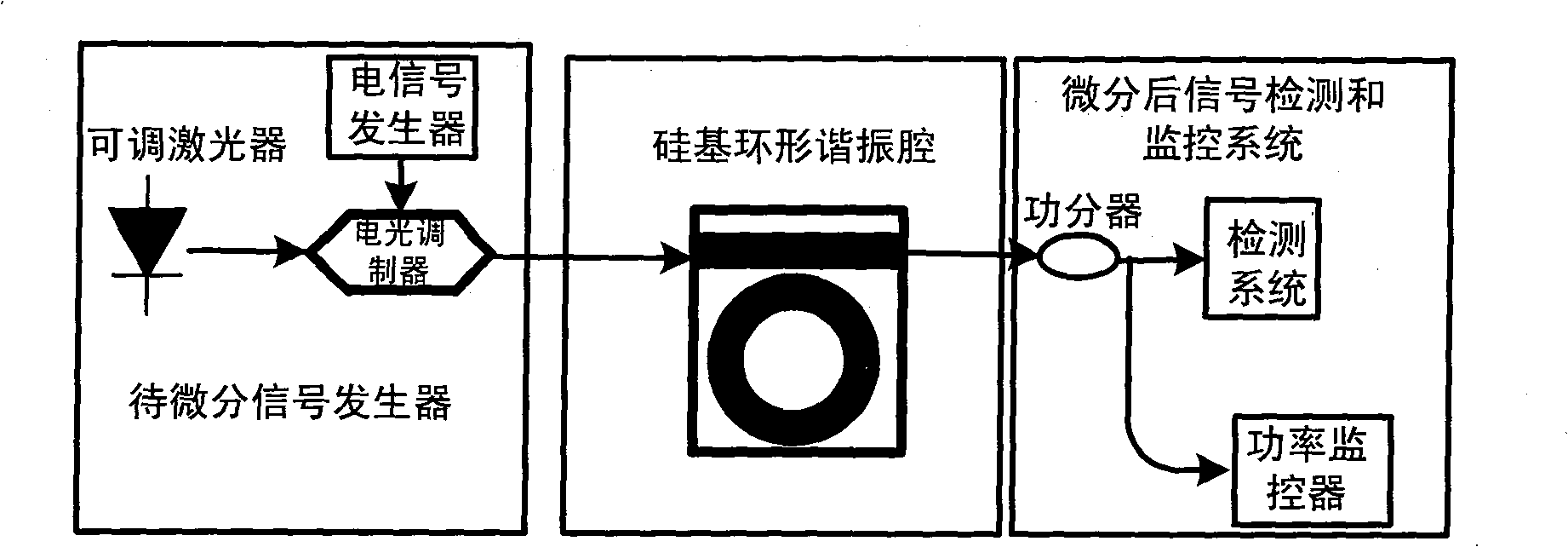
[0016] Such as figure 1 As shown, this embodiment includes: a signal generator to be differentiated, a silicon-based ring resonant cavity, and a signal detection and monitoring system after differentiation. The signal generator to be differentiated is connected with the input of the silicon-based ring resonant cavity, and the output of the silicon-based ring resonant cavity is connected with the post-differentiation signal detection and monitoring system.

[0017] The signal generator to be differentiated includes an adjustable laser, an electrical signal generator, ...


PUM


Abstract

The invention discloses an optical differentiator based on a silicon-based annular cavity resonator, which belongs to the field of optical fiber communication technology. The optical differentiator comprises a to-be-differentiated signal generator, a silicon-based annular cavity resonator, and a differentiated signal detecting and monitoring system. The silicon-based annular cavity resonator consists of a silicon-based annulet and a straight waveguide and the air-gap between the annulet and the straight waveguide is from dozens to hundreds of nanometers; the spectra of the silicon-based annular cavity resonator is characterized by periodical band-stop filtering and the transmissivity at the resonant wavelength is equal to 0 or quite close to 0. The principle of the optical differentiator is that when the silicon-based annular cavity resonator meets or is close to a critical coupling state, the spectra characteristic of the silicon-based annular cavity resonator is quite similar to the differentiator within certain range with the resonant wavelength as the center. The optical differentiator manufactured by the device has simple structure, small volume and convenient integration and can be used in an integrated all-optical signal processing system.

Description

technical field [0001] The invention relates to an optical differentiator in the technical field of optical fiber communication, in particular to an optical differentiator based on a silicon-based ring resonant cavity. Background technique [0002] All-optical signal processing is an emerging optical communication technology to address bandwidth bottlenecks encountered in high-speed electronics. Optical time-domain differentiator is an important device for all-optical signal processing. It can directly conduct first-order derivatives of optical signals to time in the optical domain. It can be used for analog-to-digital conversion, pulse shaping, optical processing of microwave signals, etc. field. At the same time, large-scale integration is becoming a development trend of optical devices. Emerging silicon-on-insulator structures provide a good platform for the integration of photonic devices. Therefore, the design of devices for all-optical signal processing functions on...

Claims


Application Information

Patent Timeline
IPC IPC(8): G02F1/35H04B10/12
Inventor 刘芳菲苏翼凯王涛李强仇旻
Owner SHANGHAI JIAO TONG UNIV
Learn More