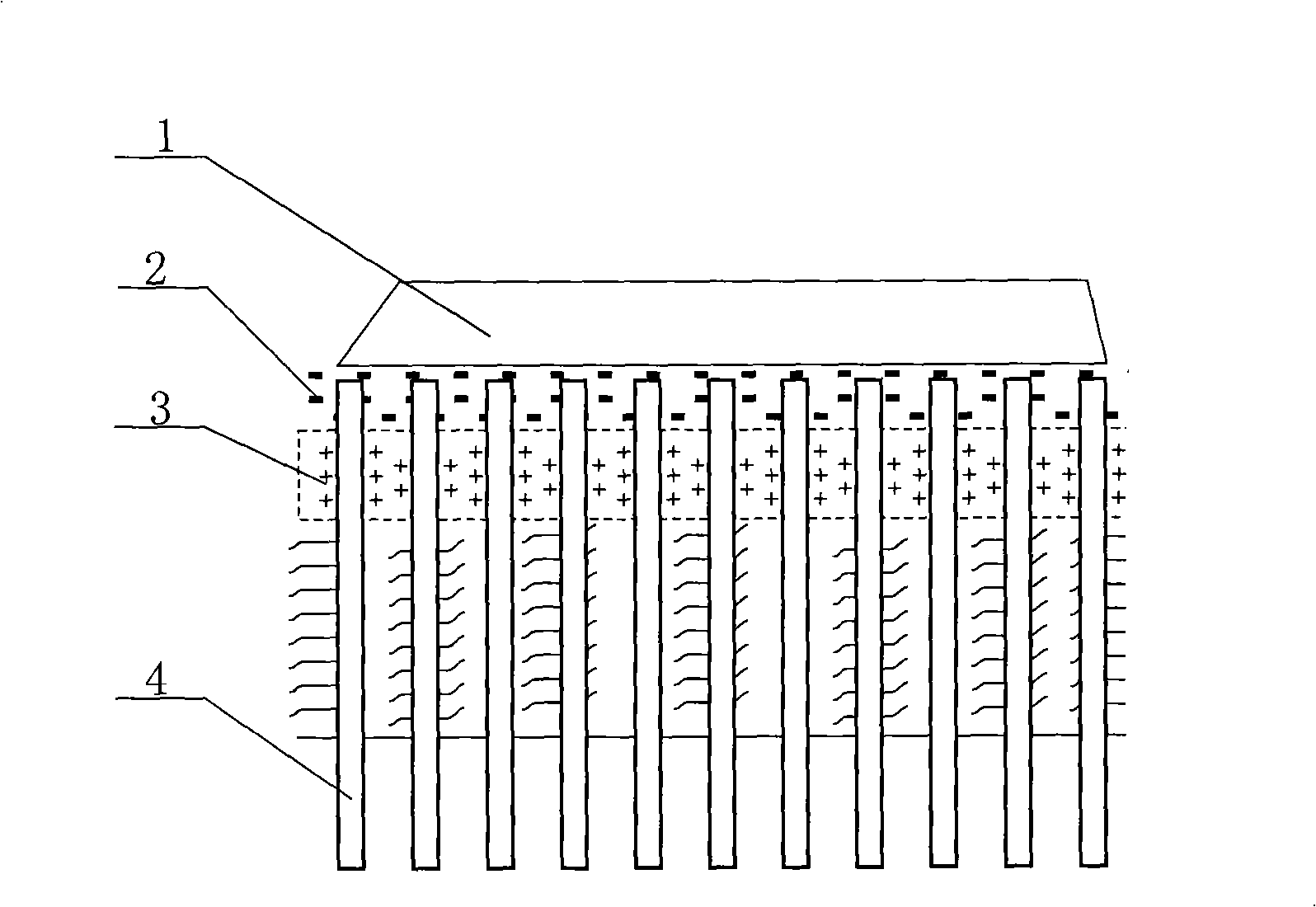
Liquified sand foundation anti-vibration processing method

A sandy soil foundation and treatment method technology, applied in soil protection, infrastructure engineering, construction, etc., can solve the problem of difficulty in ensuring the continuity and integrity of vertical drainage channels, affecting the consolidation effect of the soil layer, and soil disturbance , uplift, lateral shift, etc.

Inactive Publication Date: 2008-11-19
GUANGDONG PROVINCE HANGSHENG CONSTR GRP
View PDF0 Cites 6 Cited by
  • Summary
  • Abstract
  • Description
  • Claims
  • Application Information

AI Technical Summary

Problems solved by technology

The method of compacting sand piles is widely used because of its flexible use, simple equipment, economy, and strong adaptability to terrain fluctuations. However, in the process of compacting soil into piles, excess static pore water pressure will be generated, especially in liquefiable sand piles. When the soil and soft soil co-exist in the formation, the phenomenon of excess static pore water pressure is quite obvious. When the excess static pore water pressure generated in the process of squeezing soil into piles exceeds the bearing capacity of saturated soil, the soil will generate A series of problems such as disturbance, uplift, and lateral movement, resulting in quality defects such as pile body fracture, necking, mud inclusion, evacuation, and hanging feet of CFG piles with low lateral shear strength, making it difficult to ensure vertical drainage The continuity and integrity of the channel will seriously affect the consolidation effect of the soil layer, resulting in low seismic capacity

Method used


Image

  • Liquified sand foundation anti-vibration processing method

Examples


Embodiment 1

[0033] Shanjie Expressway adopts the anti-seismic treatment method of liquefiable sand foundation of the present invention, wherein the reinforced vertical drainage body adopted in the dynamic method is a bagged sand well, and the bagged sand well is arranged in a plum blossom shape, and the diameter of the casing is increased to The conventional 1.8 times; the spacing is reduced to 0.6 times of the conventional; the diameter of the bagged sand well is increased to 1.2 times of the conventional The spacing is 1m. The static method is surcharge preloading, which is carried on the liquefiable sand foundation with bagged sand wells. The surcharge material is earthwork. The overload is 1m, and the preloading period is more than 6 months. After the application of the present invention, the foundation of the Shanjie Expressway section has been effectively reinforced, and the preloading preloading has also reduced the post-construction settlement of the foundation soil, and the accep...

Embodiment 2

[0035] The Guangzhu West Line adopts the anti-seismic treatment method of liquefiable sand foundation of the present invention, wherein the reinforced vertical drainage body adopted in the dynamic method is a bagged sand well, and the bagged sand well is arranged in a square shape, and the diameter of the casing is increased to The conventional 1.9 times, the spacing is reduced to 0.6 times of the conventional, the diameter of the bagged sand well is increased to 1.0 times of the conventional, the diameter of the casing for drilling the bagged sand well is 140mm, the diameter of the bagged sand well is 7cm, and the sand well is specific The spacing is 0.8m. The static method is surcharge preloading, which is carried on the liquefiable sand foundation with bagged sand wells. The surcharge material is earthwork, the height of the subgrade filling is 7m, and most road sections are 1m equal load preloading. Partial road sections are overloaded by 2m, and the preloading period is 6...

Embodiment 3

[0037] The Guanghe high-speed test section adopts the anti-seismic treatment method of liquefiable sandy soil foundation of the present invention, wherein the reinforced vertical drainage body adopted in the dynamic method is a bagged sand well, and the bagged sand well is arranged in a plum blossom pattern, and the diameter of the casing is increased. It is 2 times larger than the conventional one, the spacing is reduced to 0.8 times the conventional one, and the diameter of the bagged sand well is adjusted to 1.3 times the conventional one. The specific casing diameter for drilling bagged sand wells is 170mm, the diameter of bagged sand wells is 7cm, and the specific spacing of sand wells is 0.8m; compaction technology is also used to intersperse compacted empty wells between bagged sand wells, The spacing between empty wells is 0.6m. The static method is surcharge preloading, which is carried on the liquefiable sand foundation with bagged sand wells. The surcharge material ...


PUM


Abstract

The invention relates to an earthquake-proof processing method for a liquefiable sandy soil foundation. The method adopts the technical proposal that: the technological flow of the method for integrating dynamic vibration and static loading is as follows: the dynamic vibration method is utilized to perform construction on a reinforced vertical displacement hull on the liquefiable sandy soil foundation and the static method is utilized to perform loading and prepressing. Firstly, a sand cushion is laid on the surface of the liquefiable sandy soil foundation to be as an external drainage channel of the vertical displacement hull for drainage; secondly, the type and the distribution of the reinforced vertical displacement hull are worked out, and the diameter and the space of a sleeve of the reinforced vertical displacement hull and the diameter of a sand well are determined; thirdly, the reinforced vertical displacement hull is drilled into the liquefiable sandy soil foundation; fourthly, the static method is utilized to perform loading and prepressing; and finally, loading and prepressing raw materials can adopt materials such as sand, stones, soil and so on, and the loading height depends on factors such as the properties of liquefiable sandy soil, the engineering properties, the engineering earthquake resistant design requirements and so on. The method has the advantages that: the earthquake resistance of the liquefiable sandy soil foundation is improved; the environmental pollution is reduced; and the construction cost is lower.

Description

technical field [0001] The invention relates to an anti-seismic treatment method for foundations, in particular to an anti-seismic treatment method for liquefiable sandy soil foundations, which uses a combination of dynamic vibration and static surcharge to improve the anti-seismic capability of liquefiable sandy soil foundations . Background technique [0002] At present, the commonly used anti-seismic treatment methods for liquefiable sand foundations are: dynamic compaction method, vibrating gravel pile method and compacted sand pile method. The problems and defects of these methods are as follows: [0003] The dynamic compaction method, also known as the dynamic reinforcement method, often applies an impact load to the foundation soil with an impact energy of 500-800kNm, which generates a large shock wave and dynamic stress in the foundation, so that the strength of the soil is improved, the compressibility is reduced, and the vibration liquefaction condition can be achi...

Claims


Application Information

Patent Timeline
Patent Type & Authority Applications(China)
IPC IPC(8): E02D27/34E02D3/10E02D27/26E02D19/20
Inventor 黄腾刘吉福王盛源许发明谭祥韶徐小庆
Owner GUANGDONG PROVINCE HANGSHENG CONSTR GRP
Why Eureka
Try Eureka