Jetting flow blower fan

A technology of air cooler and cold air duct, which is applied in water shower coolers, space heating and ventilation, heating methods, etc., and can solve problems such as complex structure, large wind resistance, and difficulty in defogging

Inactive Publication Date: 2008-12-03
魏仕英
View PDF2 Cites 7 Cited by
  • Summary
  • Abstract
  • Description
  • Claims
  • Application Information

AI Technical Summary

Problems solved by technology

[0004] The jet air cooler provided by the present invention is to solve the problems of the existing jet air cooler such as large wind resistance, difficult demisting and complex structure.

Method used


Image

  • Jetting flow blower fan
  • Jetting flow blower fan
  • Jetting flow blower fan

Examples


Embodiment 1

[0017] Example 1: see figure 1 , figure 2 , Figure 5, Figure 6.

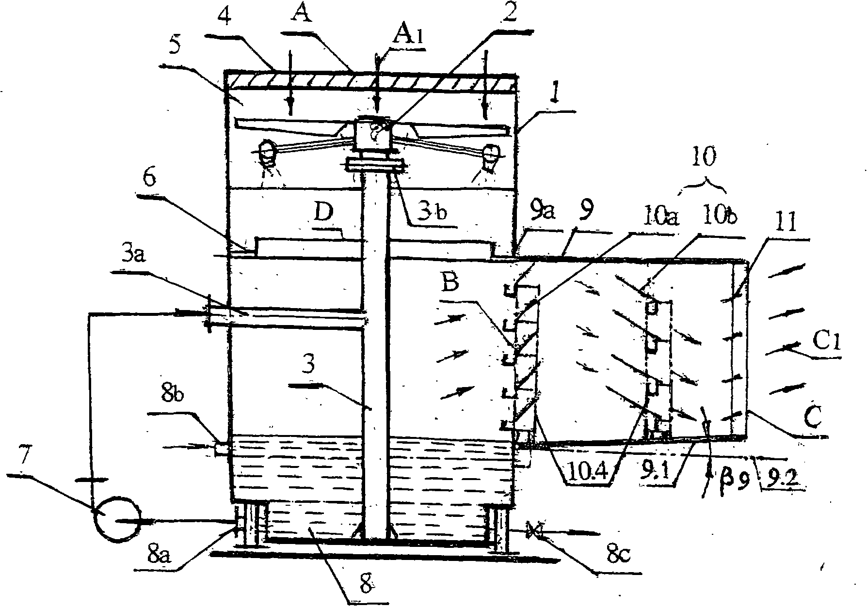
[0018] See figure 1 , in the body 1 of the jet air cooler, a demister 4 is set at the top hot air inlet A, and the cold air outlet B is set above the bottom water tank 8, where the body wall is sealed on three sides, leaving an opening, and the body side wall is extended to become The cold air passage 9, and the side wall opening 9a is sealed. There is an inclination angle β9 between the bottom surface 9.1 of the cold air duct 9 and the vertical direction 9.2 of the side wall of the water tank, that is, a backwater slope is provided between the bottom surface 9.1 and the horizon line 9.2. Two layers of water-absorbing type deflector demisters 10 are arranged in the cold air channel 9 . The tail end of the cold air passage is a cold air outlet C, and a movable air regulating plate 11 is established at C. Below the 'spray device 2', above the cold air duct 9, the center is an annular water spraying sieve pl...

Embodiment 2

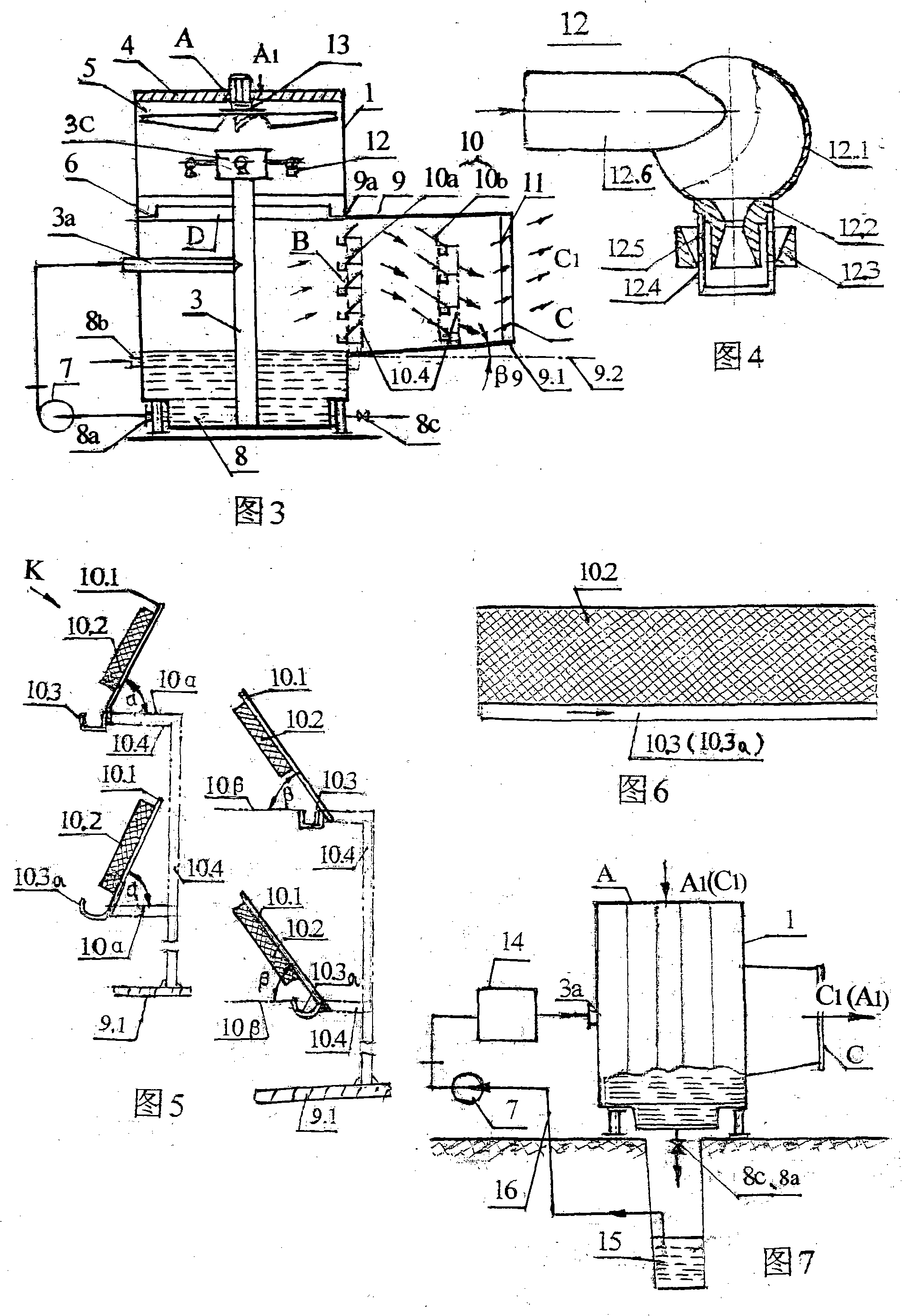
[0023] Embodiment 2: see Fig. 3, Fig. 4, mechanical ventilation jet air cooler

[0024]Compared with Example 1 except for the following structural differences, the rest are the same: see Fig. 3, the embodiment 1 'spray device 2' is replaced by the following components: 1. install a downward drafting electric fan 13 at the top air inlet A; Below 13, the cylindrical water distribution chamber 3c is adorned at the top of the water supply pipe 3; four swirl atomizing nozzles 12 (at least two) are adorned in the water distribution chamber circumferential direction. The working process is similar to that of Example 1, but the working water pressure of the swirling atomizing nozzle 12 needs to be greater than 0.12Mpa, and the power consumption of the fan 13 is added, so the energy consumption increases. But production costs have come down.

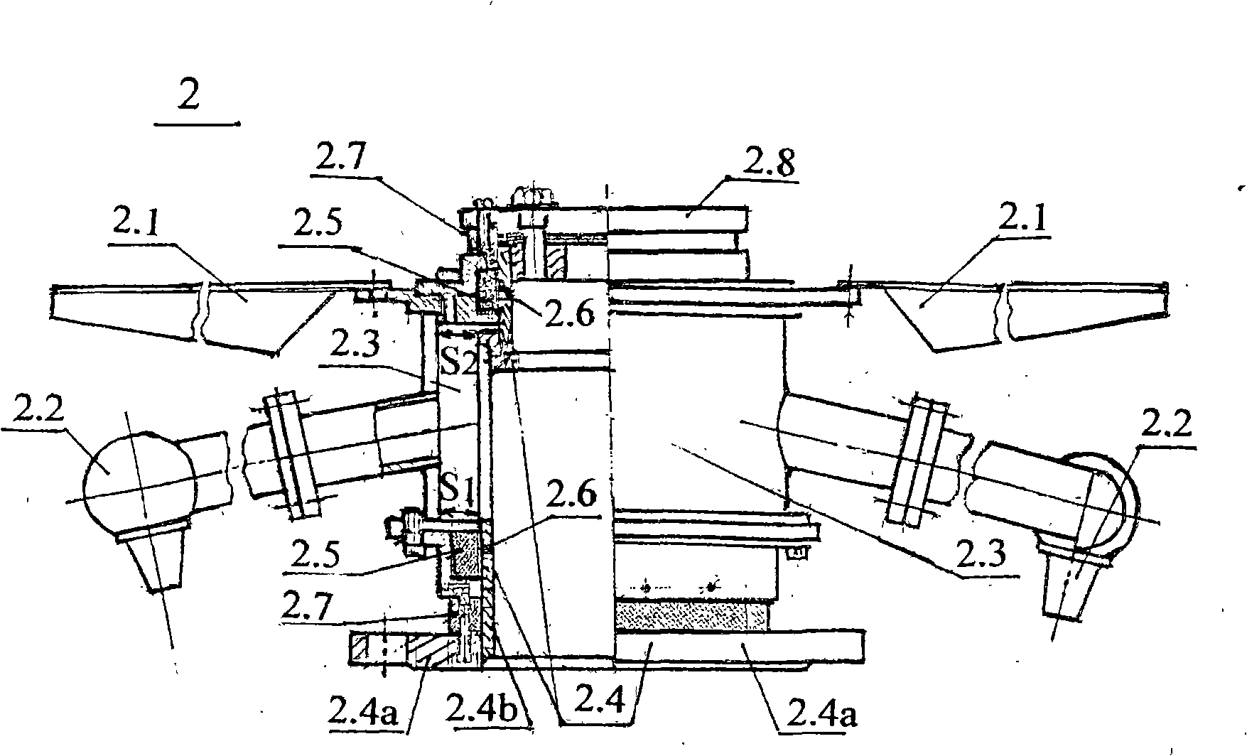
[0025] As shown in Fig. 4, the swirling atomizing nozzle 12 adopts the same lower spraying nozzle 2.2 as that in the 'spray device 2', that is,...

Embodiment 3

[0026] Embodiment 3: see Fig. 7, geothermal jet air conditioner.

[0027] Compared with Embodiment 1 except the following structural differences, the rest are the same: see Fig. 7, i. outside the body 1, a solar heater 14 is added between the water pump 7 and the water inlet pipe 3a; ii. the water inlet of the water pump 7 passes through the pipeline 16 and groundwater The well 15 is connected; iii. the water outlet pipe 8a and the drain valve 8c are arranged at the bottom of the water tank 8, and cold water or hot water is discharged into the groundwater well 15; iv. the replenishment pipe 8b installed on the side wall of the water tank 8 is canceled. In this way, a water supply and drainage circulation system is formed. Top air inlet A can take in hot air A in summer 1 Or into the cold wind in winter C 1 , the corresponding air outlet C will emit dry cold air C 1 or dry hot air A 1 .

[0028] The two-phase heat and mass transfer of air and water has the following charac...


PUM


Abstract

The invention discloses a jetting air cooler. A spray-propulsion air draft device of a lower spray nozzle and a lower air draft blade, a water-drenching sieve plate and a bottom water tank are arranged from top to bottom in the cooler body of the jetting air cooler. An air inlet at the top of the cooler body is provided with a demister; an air outlet is formed on the lateral wall of the cooler body at the upper part of the water tank; a cold air duct is extended from the air outlet; a water absorption type baffle board demister is arranged in the cold air duct; and the air draft device can also be provided with a water makeup pipe, a water outlet pipe which is connected with a water pump, etc. The low-temperature water-circulation spray is adopted by a spraying device to cool hot air into wet cold air which is further demisted into dry cold air. By adopting the normal-temperature water spray at about 20 DEG C with the difference of only 1-2 DEG C to the leaving air temperature, cold air can be obtained in summer, and warm air can be obtained in winter. According to experiments, when the water spray rate is 40m<3> / h, the pressure is 0.08 MPa, the air volume is above 2*10<4>m<3> / h, the power is only 1.4 KW.h, the water spray temperature is 24 DEG C, the atmospheric wet bulb temperature is 35 DEG C, the atmospheric dry bulb temperature is 25 DEG C, and the cold air temperature is 25 DEG C, and the refrigeration coefficient of the jetting air cooler is as high as 39.8 and is more than 10 times that of the prior air conditioner. Since the air temperature, the water temperature and the wet bulb temperature are all close to each other, the cooling water is required to be supplied in only more than 10 days which are the hottest days in one year. The jetting air cooler is suitable for low-humidity cooling and ventilation, and is an ideal water air conditioning device.

Description

(1) Technical field [0001] The invention relates to a cooling fan, which uses water as a cooling medium, uses low-pressure hydraulic power to drive the spraying and propelling atomization device, and performs spraying and pumping to realize cooling of hot air. It belongs to the heat exchange equipment category (F28C) and air conditioning category (F24F) in which the medium directly contacts without chemical reaction. (2) Background technology [0002] The characteristic of heat and mass transfer of air-water two-phase flow is that when the water temperature is higher than the air temperature, the air cools the water, and when the water temperature is lower than the air temperature, the water cools the air. And the final state is that the water temperature approaches the atmospheric wet bulb temperature. Using this principle, people invented cold water air conditioners. Existing cold water air conditioners all adopt the cooling method of atomizing nozzle and electric blower...

Claims


Application Information

Patent Timeline
Patent Type & Authority Applications(China)
IPC IPC(8): F28C1/00F24F5/00
Inventor 魏仕英魏永刚
Owner 魏仕英
Why Eureka
Try Eureka