
Short distance speed-increasing type hard rock deep borehole drilling device

A technology of deep hole drilling and speed increaser, which is used in impact drilling, rotary drilling, rotary drilling rigs, etc., can solve the problems of low efficiency, poor drilling efficiency, low drilling efficiency, etc., and achieve improvement. The effect of working environment, reducing drilling cost and improving drilling efficiency

Inactive Publication Date: 2008-12-10
JIKAI HEBEI MECHATRONICS TECH CO LTD
View PDF0 Cites 5 Cited by
  • Summary
  • Abstract
  • Description
  • Claims
  • Application Information

AI Technical Summary

Problems solved by technology

Because the drill bit needs to rotate at high speed to drill the hole, when the drill pipe is lengthened, the drill pipe and the drill bit will vibrate violently when rotating at high speed, which will not only damage the drill bit, but also cannot guarantee the straightness and accuracy of the hole when drilling deep holes. aperture, and may also pose a safety hazard
[0003] The common disadvantage of these devices is that only low speed can be used when drilling deep holes, so the drilling efficiency is very poor; when high speed, deep holes cannot be drilled.
When drilling in hard rocks, the speed is generally slow and the efficiency is low; when encountering layered rocks of different hardness or geological structures with alternating rock layers and soil layers, the drilled holes cannot meet the requirements
Drilling is the preliminary work for other operations, and the low efficiency of drilling will affect the progress and speed of other operations

Method used


Image

  • Short distance speed-increasing type hard rock deep borehole drilling device
  • Short distance speed-increasing type hard rock deep borehole drilling device

Examples


Embodiment Construction

[0019] Below in conjunction with accompanying drawing, the present invention is described in further detail:

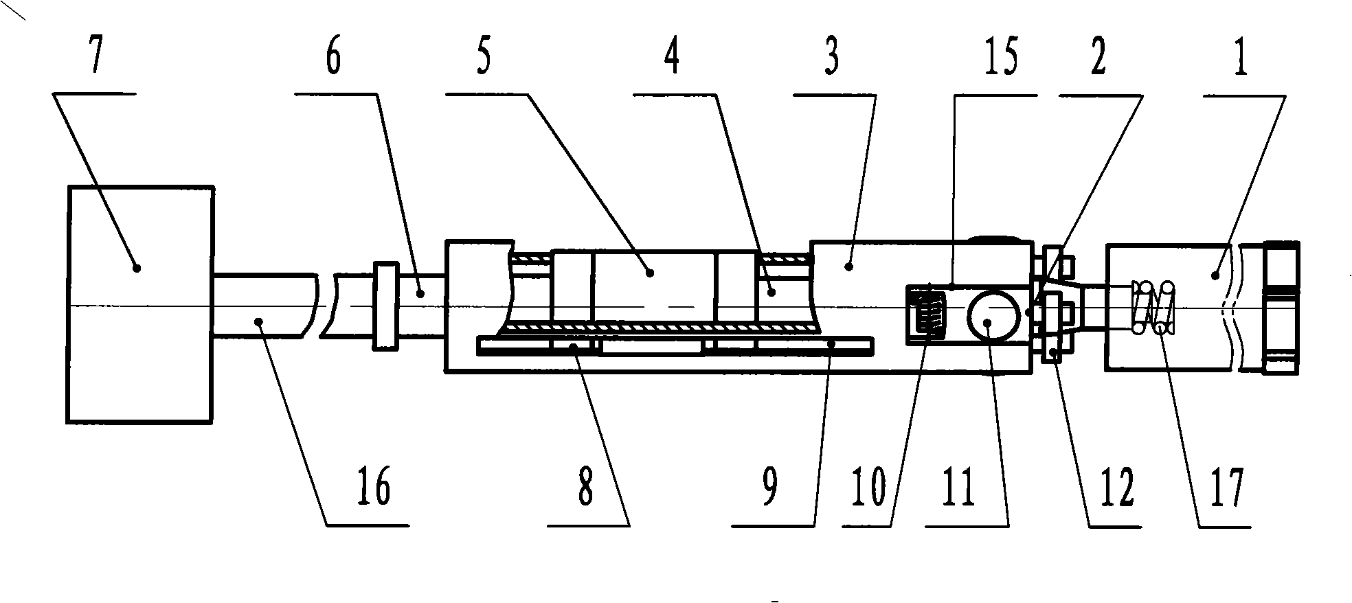
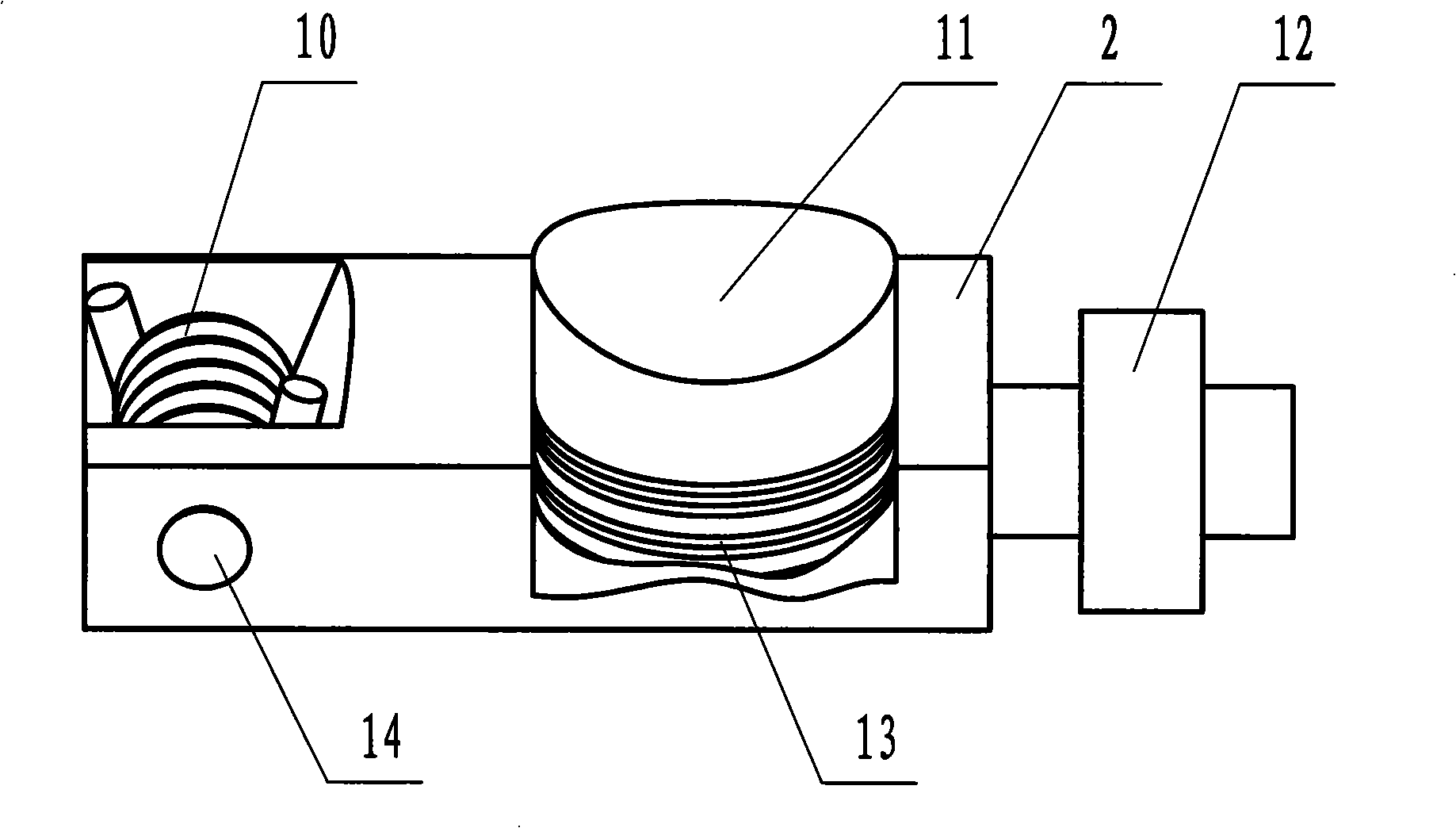
[0020] The structure of the present invention is as figure 1 As shown, it comprises a diamond drill bit 1 and a drilling rig 7 for drilling power, the power output shaft of the drilling rig 7 is connected with a drill rod 16; One end of 5 connects input shaft 6, and input shaft 6 is connected with drilling machine 7, and along with the deepening of borehole, between drilling machine 7 and input shaft 6, gradually connect the drilling rod of different length again. The other end of speed increaser 5 is provided with output shaft 4, and output shaft 4 is movably connected with drill bit 1, and the position that output shaft 4 is connected with drill bit 1 is provided with compression spring 17. The input shaft 6, the output shaft 4 and the speed increaser 5 are internally provided with interconnected water holes. The water holes lead to the inside of the diamond drill ...


PUM


Abstract

The invention discloses a near-distance acceleration device for drilling deep holes in hard rock, which belongs to the field of drilling machines. An accelerator is arranged close to a drill bit; one end of the accelerator is an input shaft which is connected with a drilling machine; the other end of the accelerator is provided with an output shaft which is connected with the drill bit. The outside of the accelerator is provided with a sleeve; one end of the sleeve which is close to the drill bit is provided with a supporting hole wall and a movable jack catch used to fix the sleeve; the jack catch is provided with a bearing which contacts and is matched with the output shaft; a sliding key on the accelerator is matched with a sliding keyway on the sleeve; through holes which are communicated are arranged in the input shaft, the output shaft and the accelerator and communicated with the inside of the drill bit. The drilling device accelerates the drill bit only at the positions close to the drill bit in the deep holes, so that the drill bit can rotate and cut in the deep holes at high speed; the input shaft and a drill pipe rotate at low speed, so the drill pipe and the drill bit do not shake dramatically, which can not only ensure the liberality of the holes and the precision of the aperture, but also prolong the service life of the drill bit and improve the drilling efficiency.

Description

technical field [0001] The invention relates to a drilling tool, in particular to a short-distance speed-up type hard rock deep hole drill used for drilling in rocks. Background technique [0002] Drilling holes in rocks is a very important job in mining, construction, tunneling and other industries, such as anchor cable holes, blast holes, installation holes, etc., all need to drill holes in rocks. There are many equipment and tools for drilling, such as hydraulic drilling rigs, pneumatic drilling rigs, percussion drilling rigs, and various carbide drill bits and diamond drill bits. These drilling equipment all are to directly install drill bit on the output shaft of drilling rig, or then install extension drilling rod on the output shaft of drilling rig in order to drill deep hole, then drill bit is connected to the front end of drilling rod. The drilling rig is a device that provides power, and its volume is relatively large, so it can only stay outside the drilled hole....

Claims


Application Information

Patent Timeline
IPC IPC(8): E21B3/00
Inventor 冯春保李占利刘占宏刘水东李伟
Owner JIKAI HEBEI MECHATRONICS TECH CO LTD
Learn More