Control apparatus and method for motor drive system

A technology for controlling equipment and driving systems, which is applied in the control of motor vibration, motor generator control, AC motor control, etc., to prevent torque fluctuations and improve accuracy.

Inactive Publication Date: 2008-12-17
TOYOTA JIDOSHA KK
View PDF2 Cites 27 Cited by
  • Summary
  • Abstract
  • Description
  • Claims
  • Application Information

AI Technical Summary

Problems solved by technology

However, there is no description related to these measures in Japanese Patent Application Publication JP-A-11-299297

Method used


Image

  • Control apparatus and method for motor drive system
  • Control apparatus and method for motor drive system
  • Control apparatus and method for motor drive system

Examples


Embodiment Construction

[0041] In the following description and accompanying drawings, the invention will be described in detail with reference to exemplary embodiments. The same or corresponding parts will be denoted by the same reference numerals and will be explained basically only once.

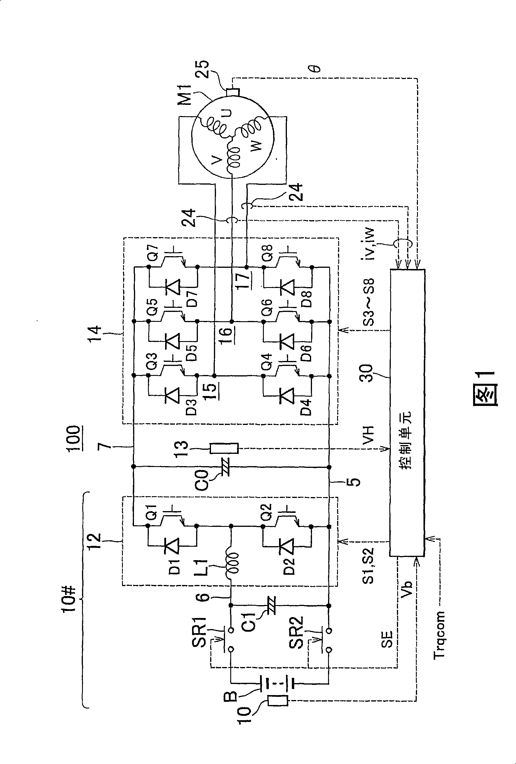
[0042] FIG. 1 shows the overall configuration of a motor drive system according to an embodiment of the present invention. As shown in FIG. 1, the motor driving system 100 according to this embodiment of the present invention includes a DC voltage generating portion 10#, a smoothing capacitor C0, an inverter 14, and an AC motor M1.

[0043] AC motor M1 is a drive motor that generates torque for driving drive wheels of a hybrid vehicle or an electric vehicle. Alternatively, the AC motor M1 may also be configured to function as a generator driven by the engine. Alternator M1 can be configured to function as both a motor and a generator. The AC motor M1 may serve as an electric motor for the engine, and may be i...


PUM


Abstract

In the rectangular-wave voltage control mode, torque feedback control, in which the voltage phase (phiv) of the rectangular-wave voltage is adjusted based on the deviation of the torque estimated value (Trq) from the torque command value (Trqcom), is performed. A torque estimation portion (420) calculates the torque estimated value (Trq) using the motor currents (Id, Iq) calculated based on the values detected by a current sensor (24) and a rotational position sensor (25), as in the case of the PWM control mode. Namely, the same state quantity (quantity detected by the sensors) of the alternating-current motor (M1) is used in the motor control in both the rectangular-wave voltage control mode and the PWM control mode.

Description

technical field [0001] The present invention generally relates to control apparatus and methods for motor drive systems. More particularly, the present invention relates to a control apparatus and method for a motor driving system that converts DC voltage into AC voltage with an inverter to drive and control an AC motor. Background technique [0002] A motor drive system is often used that uses an inverter to convert DC voltage to AC voltage to drive a three-phase AC motor. Various control modes for appropriately controlling the torque output from the AC motor to a target torque (torque command value) in such a motor drive system have also been proposed. [0003] For example, Japanese Patent Application Publication JP-A-2005-124359 describes a method in which, in current feedback for current control of a synchronous motor, the current signal evaluated by an observer with a correction term is used to compare the actual speed with the estimated The error between speeds is co...

Claims


Application Information

Patent Timeline
Patent Type & Authority Applications(China)
IPC IPC(8): H02P6/08H02P6/10H02P21/14H02P21/00H02P6/06H02P6/15H02P6/17H02P6/28H02P21/05H02P21/18H02P21/22H02P21/24H02P23/04H02P23/12H02P23/14H02P25/026H02P27/04H02P27/08
CPCB60L15/025B60L15/08B60L2210/12B60L2210/14B60L2210/20B60L2240/421B60L2240/423B60L2260/44H02P2201/09Y02T10/64Y02T10/72H02P6/10H02P21/00H02P21/14H02P27/04
Inventor 佐藤亮次
Owner TOYOTA JIDOSHA KK
Why Eureka
Try Eureka