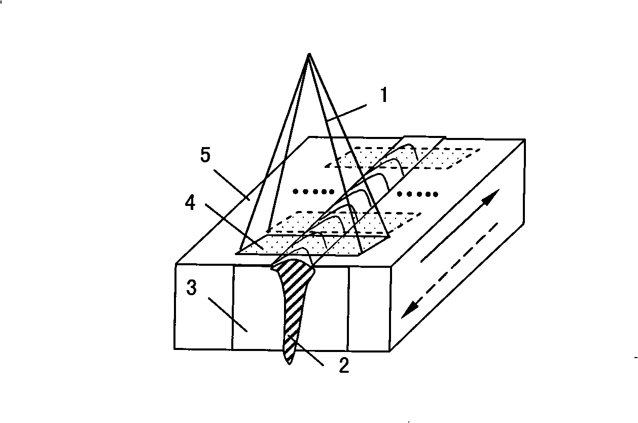
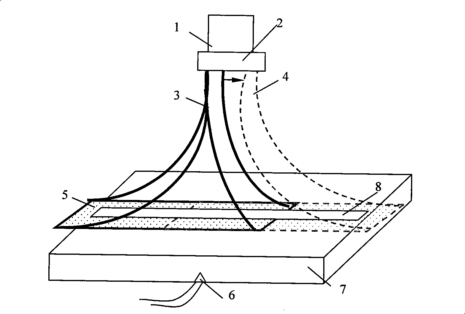
Double electron beam partial heat treatment method after refractory metal material is welded
A local heat treatment, metal material technology, applied in electron beam welding equipment, metal processing equipment, welding equipment, etc., can solve the problems of inability to meet the solid solution temperature, poor heat treatment uniformity, etc.
- Summary
- Abstract
- Description
- Claims
- Application Information
AI Technical Summary
Problems solved by technology
Method used
Image
Examples
Embodiment 1
[0044] Select a board with a size of 100×80×6mm:
[0045] (1) Electron beam welding process:
[0046] Parameters: Acceleration voltage U a =60kV, beam current I b =41mA, focusing current I f =772mA, welding speed V=800mm / min, vacuum degree 3×10 -2 ~8×10 -2 Pa, the distance between the gun and the surface of the workpiece H = 300mm.
[0047] (2) Electron beam partial solution heat treatment:
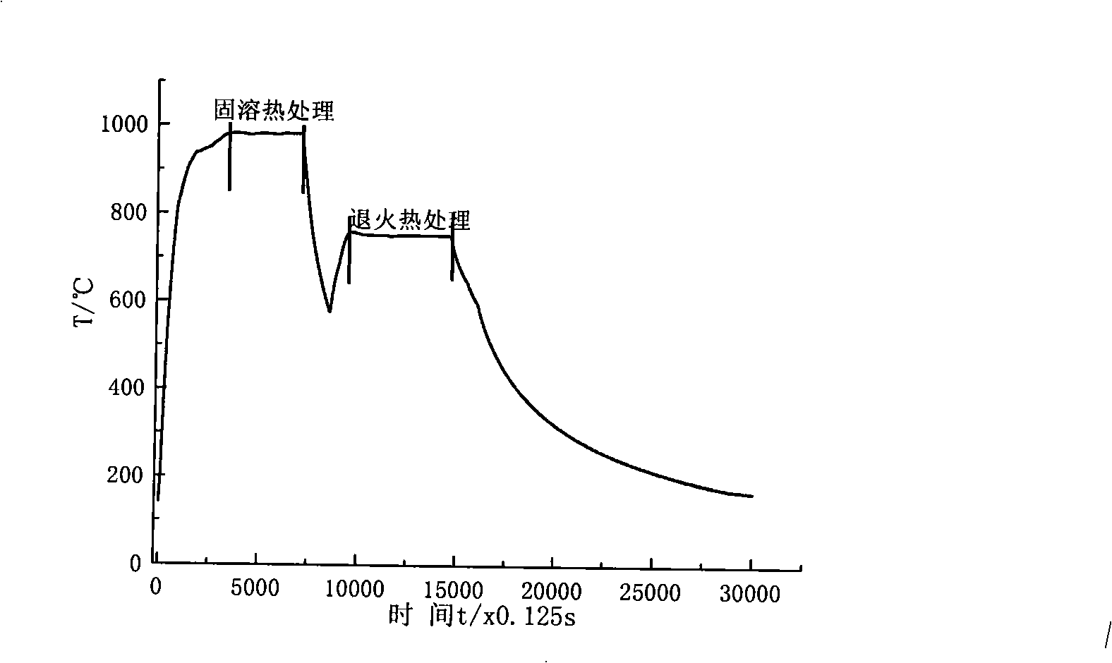
[0048] Adjust the movement system of the electron gun so that the distance between the coil and the workpiece is H r =449mm; acceleration voltage U a =60kV, beam current: the maximum beam current I for heating and heating bmax =26mA, beam current I in heat treatment stage b =20mA, focusing current I f =797mA, scanning area: length Y=25mm vertically to the weld seam direction, X=130mm length along the weld seam direction. The maximum temperature T on the surface of the test piece during the solution heat treatment process is monitored by an optical thermometer smax = 1120°C, el...
Embodiment 2
[0052] Select a board with a size of 100×80×6mm:
[0053] (1) Electron beam welding process:
[0054] Parameters: Acceleration voltage U a =60kV, beam current I b =41mA, focusing current I f =770mA, welding speed V=800mm / min, vacuum degree 3×10 -2 ~8×10 -2 Pa, the distance between the gun and the surface of the workpiece H = 300mm.
[0055] (2) Electron beam partial solution heat treatment:
[0056] Adjust the movement system of the electron gun so that the distance between the coil and the workpiece is H r =449mm; acceleration voltage U a =60kV, beam current: the maximum beam current I for heating and heating bmax =22mA, beam current I in heat treatment stage b =18mA, focusing current I f =795mA, scanning area: length Y=25mm along the vertical direction of the welding seam, length X=130mm along the direction of the welding seam.
[0057] The maximum temperature T of the upper surface of the specimen during solution heat treatment smax =1100°C, electron beam local ...
Embodiment 3
[0061] Select a board with a size of 100×80×14mm
[0062] (1) Welding process:
[0063] Parameters: Acceleration voltage U a =60kV, beam current I b =86mA, focusing current I f =772mA, welding speed V=800mm / min, vacuum degree 3×10 -2 ~8×10 -2 Pa, the distance between the gun and the surface of the workpiece H = 300mm.
[0064] (2) Electron beam partial solution heat treatment:
[0065] Adjust the movement system of the electron gun so that the distance between the coil and the workpiece is H r =449mm; acceleration voltage U a =60kV, beam current: the maximum beam current I for heating and heating bmax =40mA, beam current I in heat treatment and heat preservation stage b =27mA, focusing current I f =797mA, scanning area: length Y=25mm vertically to the weld seam direction, X=130mm length along the weld seam direction. The highest temperature on the surface of the test piece T smax =1120℃, realized electron beam local solution heat treatment at 980℃ for 10min, such a...
PUM
 Abstract
Description
Claims
Application Information
 - R&D
- Intellectual Property
- Life Sciences
- Materials
- Tech Scout
- Unparalleled Data Quality
- Higher Quality Content
- 60% Fewer Hallucinations
Browse by: Latest US Patents, China's latest patents, Technical Efficacy Thesaurus, Application Domain, Technology Topic, Popular Technical Reports.
© 2025 PatSnap. All rights reserved.Legal|Privacy policy|Modern Slavery Act Transparency Statement|Sitemap|About US| Contact US: help@patsnap.com


