
Electroforming composite processing apparatus and electroforming tank used by the apparatus

A combined processing and electroforming tank technology, applied in the direction of electroforming and electrolysis, can solve the problems of low current density, poor uniformity of electroforming layer, low structure density, etc., to achieve enhanced impact and disturbance, and reduce concentration extremes The effect of chemicalization and tissue uniformity and compactness

Inactive Publication Date: 2011-06-29
HENAN UNIV OF SCI & TECH
View PDF0 Cites 0 Cited by
  • Summary
  • Abstract
  • Description
  • Claims
  • Application Information

AI Technical Summary

Problems solved by technology

However, there are also some defects and limitations in electroforming, mainly in: (1) Due to the edge effect of the current, the power lines are easy to concentrate at the sharp corners and edges of the mandrel, and the shielding effect of the side wall of the groove on the bottom of the groove , resulting in relatively sparse power lines at the bottom of the tank, resulting in poor uniformity of the electroforming layer and low tissue density; (2) During the deposition of metal ions, hydrogen and other gases precipitated from the surface of the cathode will stay on the surface of the cathode and cause hydrogen embrittlement, resulting in Defects such as pitting and nodules appear on the surface of the casting layer, which reduces the deposition rate of the metal; (3) Due to the low current density applicable to electroforming, the deposition rate of the metal is slow, resulting in a long processing cycle, etc.

Method used


Image

  • Electroforming composite processing apparatus and electroforming tank used by the apparatus
  • Electroforming composite processing apparatus and electroforming tank used by the apparatus
  • Electroforming composite processing apparatus and electroforming tank used by the apparatus

Examples


Embodiment Construction

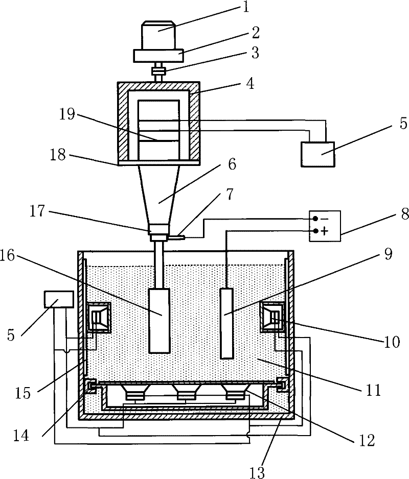
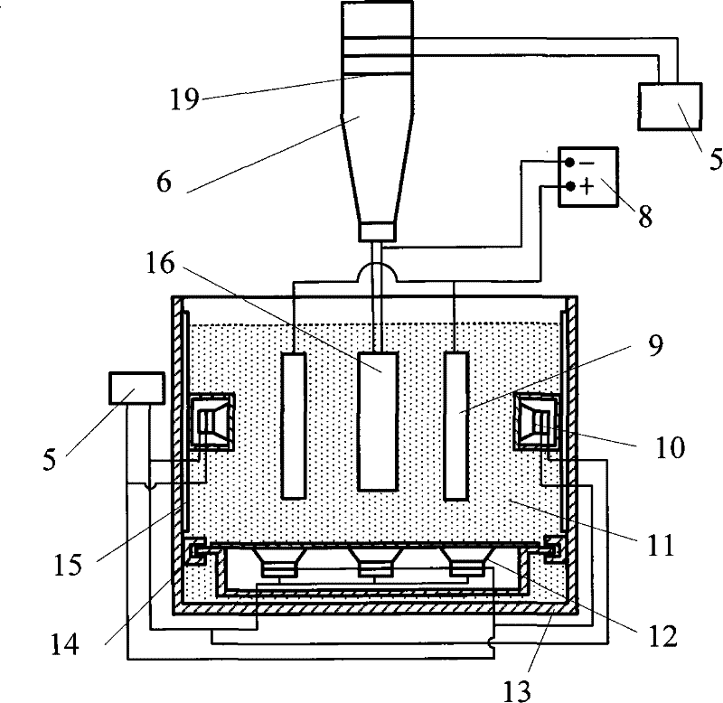
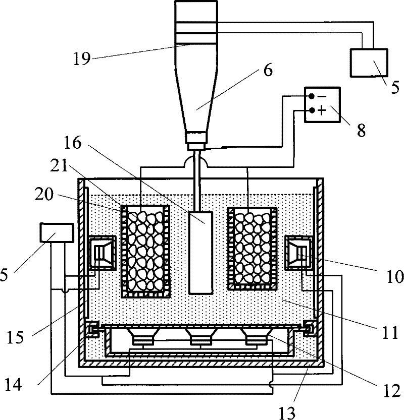
[0013] Figure 1 ~ Figure 3 Winning marks: 1. Motor, 2. Reduction device, 3. Coupling, 4. Hollow sleeve, 5. Ultrasonic generator, 6. Horn, 7. Carbon brush, 8. Power supply, 9. Anode, 10 , Transducer row on the tank side, 11, electroforming liquid, 12, transducer row on the bottom of the tank, 13, electroforming tank, 14, sliding track at the bottom of the tank, 15, sliding track on the tank side, 16, electroforming mandrel ( cathode), 17, connector, 18, flange, 19, transducer, 20, hanging basket, 21, granular anode.

[0014] figure 1 It is a schematic diagram of the electroforming composite processing device, including an electroforming mandrel supporting device and an electroforming tank 13, a transducer device is arranged on the electroforming mandrel supporting device and in the electroforming tank, and the transducer device The energy device is electrically connected with each ultrasonic generator 5. As a typical implementation, it is better to install a transducer devi...


PUM


Abstract

The invention relates to an electroforming combined processing device. The device comprises an electroforming mandrel supporting device and an electroforming groove (13), wherein, an energy transducer device is arranged on the electroforming mandrel supporting device and inside the electroforming groove (13), and the energy transducer device of the electroforming groove (13) is arranged on a sidewall surface and / or a bottom surface in the electroforming groove (13), an energy transducer of the energy transducer device is electric connection with an ultrasonic generator (5), the ultrasonic generator (5) is an ultrasonic generator with adjustable frequency, the energy transducer device in the electroforming groove (13) is formed by a sealing box and an energy transducer row, each energy transducer row is respectively attached to one side of the sealing box towards the electroforming groove (13), the sealing box of the energy transducer device on the sidewall surface of the electroforming groove (13) is movably fixed on the sidewall surface through a side sliding track (15) fixed on the side surface, and the sealing box of the energy transducer device on the bottom surface of the electroforming groove (13) is movably fixed on the bottom surface through a bottom sliding track (14) fixed on the bottom. The electroforming device of the invention improves the quality of the electroforming product.

Description

technical field [0001] The invention relates to an electroforming composite processing device and an electroforming tank for the device, belonging to the field of electroforming processing, and relates to an electroforming composite processing device that applies multi-frequency ultrasonic coupling to the electroforming process to improve the quality of electroforming products. Background technique [0002] Electroforming is a special processing method that uses the principle of electrodeposition of metal ions on the surface of the cathode to accurately replicate certain complex or special-shaped workpieces. Electroforming has a wide range of application prospects in industrial fields such as aviation, aerospace, weapons, precision instruments and meters, and biomedical equipment due to its high replication accuracy and repeatability. However, there are also some defects and limitations in electroforming, mainly in: (1) Due to the edge effect of the current, the power lines ...

Claims


Application Information

Patent Timeline
Patent Type & Authority Patents(China)
IPC IPC(8): C25D1/00
Inventor 薛玉君李济顺马伟葛述卿刘红彬
Owner HENAN UNIV OF SCI & TECH
Learn More