Chemiluminescent detection system
A measurement device, chemiluminescence technology, applied in measurement devices, chemiluminescence/bioluminescence, chemical instruments and methods, etc., can solve the problems of inability to supply, change in luminescence intensity, sequence determination or DNA detection accuracy, and achieve analytical production. The effect of improving the quantity and measuring sensitivity
- Summary
- Abstract
- Description
- Claims
- Application Information
AI Technical Summary
Problems solved by technology
Method used
Image
Examples
Embodiment 1
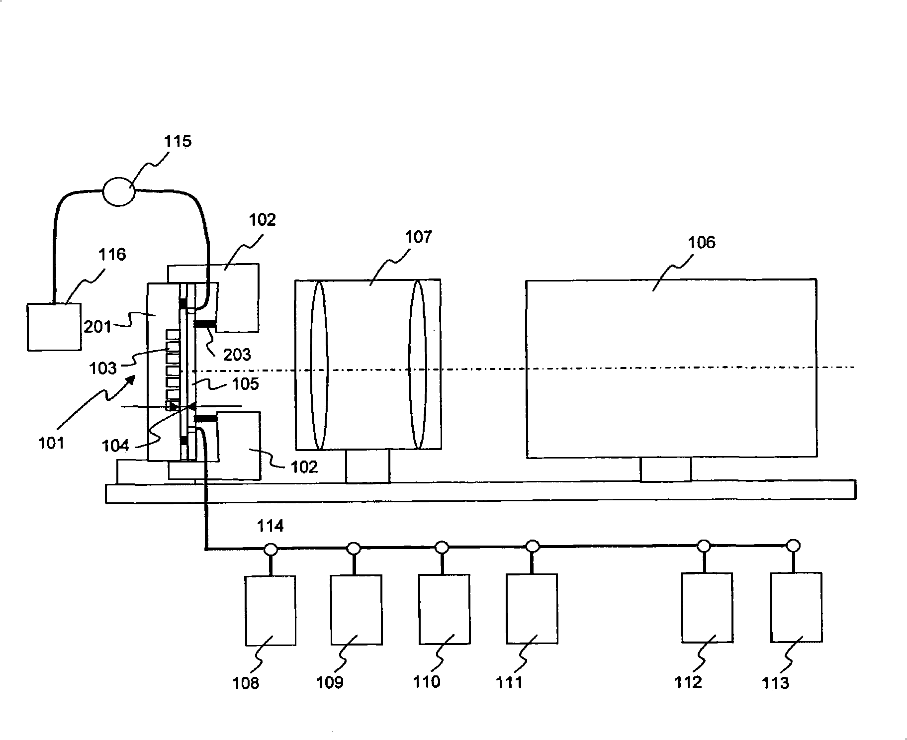
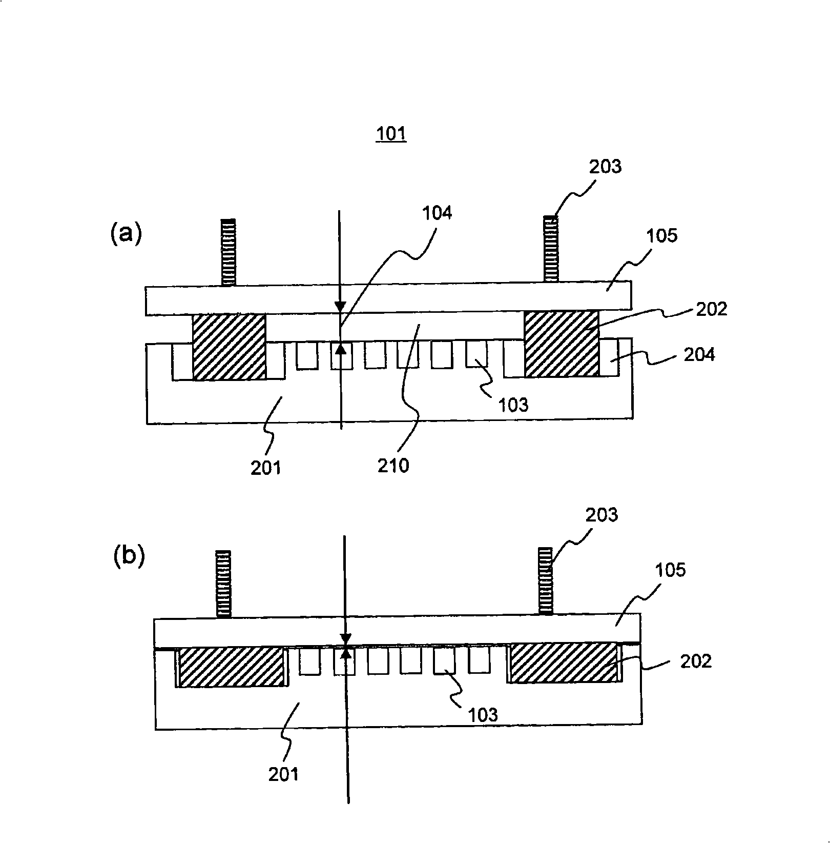
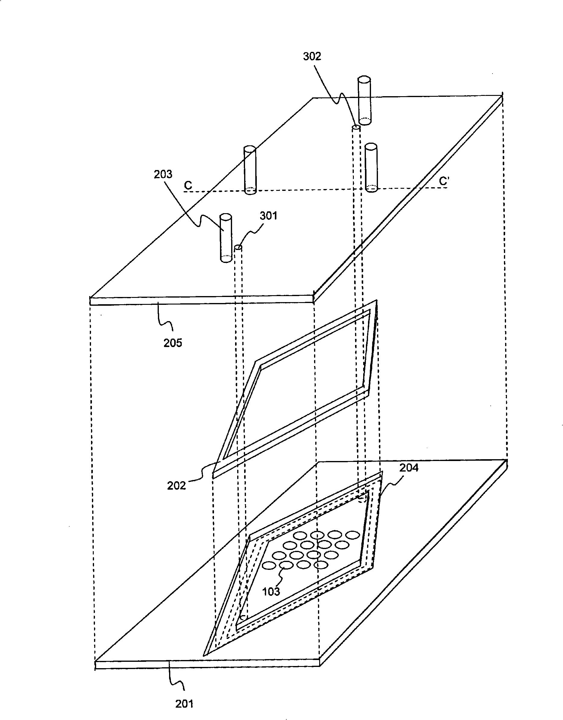
[0073] figure 1 It is a diagram showing a configuration example of the chemiluminescence measurement device of the present invention. In the chemiluminescence measurement device of this embodiment, various reagents are poured into the flow cell 101 formed by the plate 201 provided with a plurality of micro reaction tanks and the transparent substrate 105, by measuring Chemiluminescence in the reaction tank 103 to determine the base sequence. In the present invention, when measuring chemiluminescence and when flowing reagents to supply reagents to the micro-reaction tanks, the thickness of the reagent flow path is changed to change the conductance, cross-sectional shape, and cross-sectional area of the flow path. Accordingly, when measuring chemiluminescence, the luminous density is increased while suppressing crosstalk with adjacent micro-reaction tanks, thereby improving the measurement sensitivity of luminescence. In addition, when supplying reagents to the micro-reactio...
Embodiment 2
[0092] In Example 1, the thickness of the flow path was changed by elastically deforming the spacer, thereby suppressing the diffusion of the product from the micro-reaction tank. The same effect as in Example 1 was obtained by changing the thickness of the flow path immediately above the micro reaction tank.
[0093] Figure 8 A schematic cross-sectional view showing another example of the flow cell. The flow cell of this example is a flow cell in which stress can be applied to the transparent substrate 701 to bend it, thereby reducing the thickness of the flow path directly above the micro reaction tank 103 . Figure 8 (a) is a diagram showing a state where no stress is applied, Figure 8 (b) is a diagram showing a state where stress is applied and the thickness of the flow path is reduced. In the present embodiment, by thinning a part of the transparent substrate 701 serving as the upper plate, it has a shape that is easily deformed when stress is applied by the rod 203 ...
Embodiment 3
[0100] In this embodiment, instead of moving and deforming the transparent substrate and plate, other transparent substrates are placed in the flow path of the flow cell to suppress the diffusion of the product from the micro reaction tank. Figure 11 A system configuration example of a chemiluminescence measurement device is shown. Set electromagnet 1001 to replace figure 1 The rod 203, the driving part 1002 is provided to support and drive the electromagnet instead of the driving part 102.
[0101] Figure 12 (a) A schematic cross-sectional view showing a state in which the thickness of the flow channel of the flow cell of this example is thickened, Figure 12 (b) shows a schematic cross-sectional view in a state where the channel thickness is reduced. A transparent substrate 1101 made of polypropylene is installed in the flow path, and the surface of a neodymium magnet (main components: neodymium, iron, boron) 1102 is covered with polypropylene with a thickness of about ...
PUM
| Property | Measurement | Unit |
|---|---|---|
| diameter | aaaaa | aaaaa |
| thickness | aaaaa | aaaaa |
| thickness | aaaaa | aaaaa |
Abstract
Description
Claims
Application Information
 - R&D
- Intellectual Property
- Life Sciences
- Materials
- Tech Scout
- Unparalleled Data Quality
- Higher Quality Content
- 60% Fewer Hallucinations
Browse by: Latest US Patents, China's latest patents, Technical Efficacy Thesaurus, Application Domain, Technology Topic, Popular Technical Reports.
© 2025 PatSnap. All rights reserved.Legal|Privacy policy|Modern Slavery Act Transparency Statement|Sitemap|About US| Contact US: help@patsnap.com


