
Combined positron emission tomography/magnetic resonance imaging apparatus

A technology of positron emission and magnetic resonance tomography, which is applied in the direction of instruments for radiological diagnosis, diagnosis, echo tomography, etc.

Inactive Publication Date: 2008-12-31
SIEMENS AG
View PDF4 Cites 8 Cited by
  • Summary
  • Abstract
  • Description
  • Claims
  • Application Information

AI Technical Summary

Problems solved by technology

[0005] Therefore, there is a problem that the vibration (tens of g) of the surface of the gradient coil is transmitted to the PET holder with little attenuation

Method used


Image

  • Combined positron emission tomography/magnetic resonance imaging apparatus
  • Combined positron emission tomography/magnetic resonance imaging apparatus

Examples


Embodiment Construction

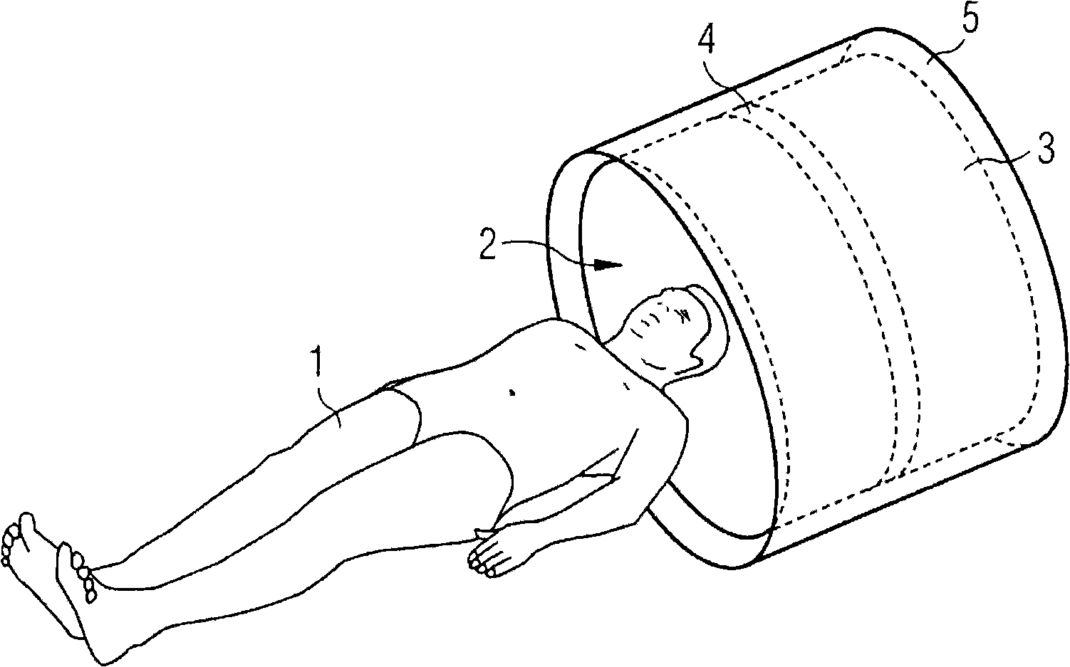
[0025] as in figure 1 As shown in , the examination object 1 is placed in the examination space 2 in the combined PET and MRT. The examination space 2 is surrounded by a PET system 3 with a detector arrangement 4 . The detector arrangement 4 is typically an arrangement of scintillation crystals (not shown), which are arranged annularly around the examination space 2 . Inside the scintillation crystal, a photon with an energy of 511 keV (the annihilation radiation of the positron) is converted into a photon, which in turn is guided onto a photodetector (not shown), preferably via an optical waveguide (not shown) , the photodetector generates an output electrical signal related to the number of photons.

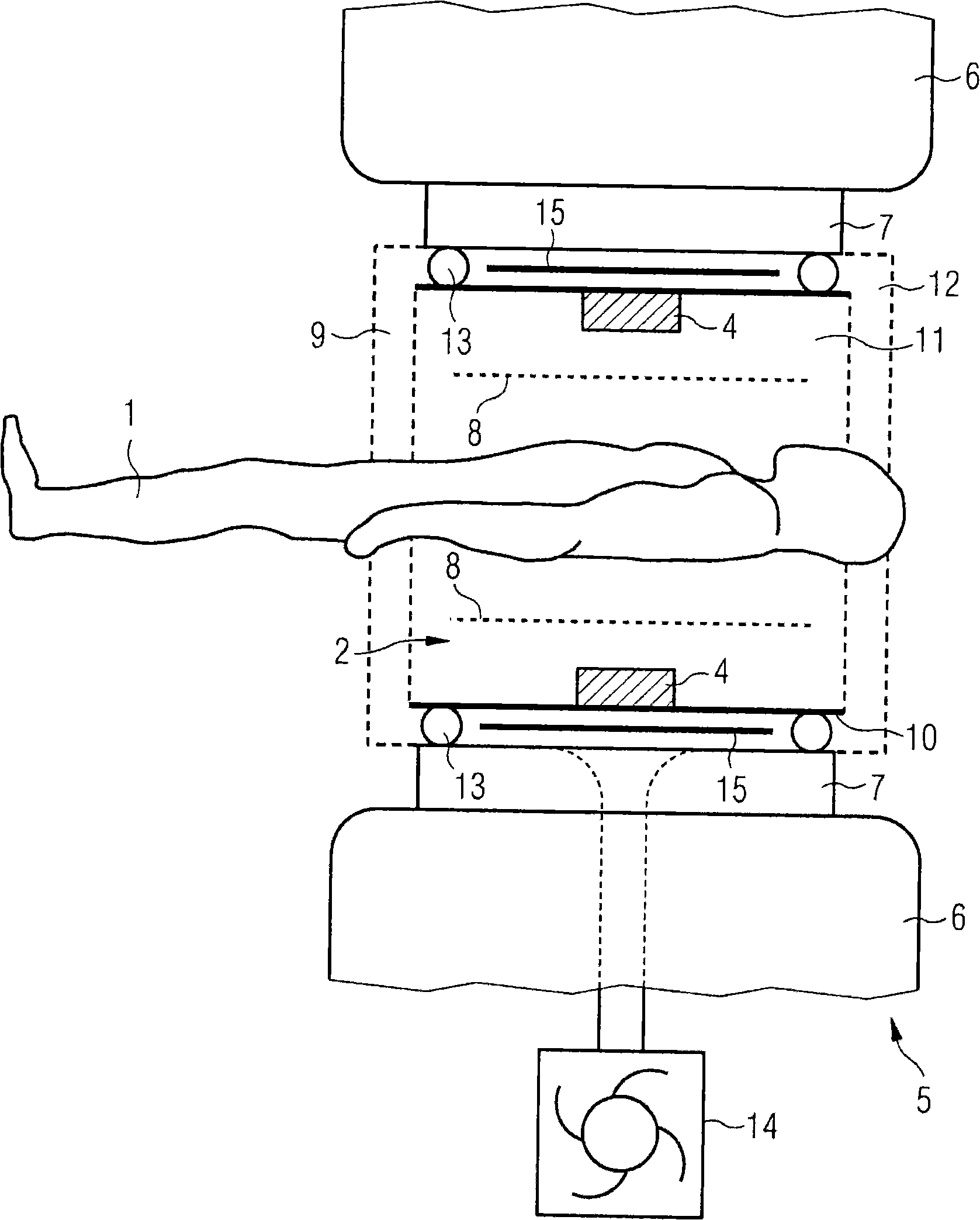
[0026] In order to improve the local resolution of the examination performed on the examination object 1 , the PET system is surrounded by an MRT system 5 . In addition to the basic field magnet 6 , the MRT system 5 essentially includes a gradient coil 7 and a radio-frequenc...


PUM


Abstract

The present invention relates to a combined positron emission tomography-magnetic resonance imaging apparatus, which comprises a positron emission tomography apparatus (3) having at least one radiation detector (4), and a magnetic resonance imaging apparatus having at least one gradient coil (6) and a high-frequency antenna device (8). In order to prevent mechanical vibration being induced in the PET gantry by the gradient coil, the combined position emission tomography-magnetic resonance imaging apparatus according to the present invention is developed in that a first molding part (7) is provided, the surface of which coincides with the inner shell (9) of the at least one gradient coil (6), and a second molding part (10) is provided, the surface of which coincides with the outer shell (11) of the radiation detector (4), the distance between the two shells (9, 11) is virtually constant over the circumference of the shells, and a vacuum seal (13) is respectively arranged along at least a first circumferential line and a second circumferential line such that a closed cavity is formed between the vacuum seals.

Description

technical field [0001] The invention relates to a combined positron emission-magnetic resonance tomography apparatus for imaging internal organs of an examination object. Background technique [0002] For example, US Pat. No. 4,939,464 is known to combine magnetic resonance (MR) examinations with positron emission tomography (PET) in one device under conditions of the same imaging field. In this prior art, the optical signal of the scintillation crystal is passed out from the measurement space to the photodetector via an optical waveguide. The photodetector is arranged outside the measurement space, since the photodetector must be protected from interaction with the magnetic fields required for the MR examination. [0003] Furthermore, a combined positron emission tomography and magnetic resonance tomography device is known from DE 102005015070, which has a positron emission tomography device and a magnetic resonance tomography device. In this prior art, for the purpose of...

Claims


Application Information

Patent Timeline
IPC IPC(8): G01R33/385A61B5/055
CPCA61B6/037A61B6/4417G01R33/481G01R33/56509
Inventor 路德维格·克赖彻于尔根·尼斯特勒马丁·劳施沃尔夫冈·伦兹诺伯特·里奇
Owner SIEMENS AG
Learn More