Optical fiber ring quality measurement method and its device for optical fibre gyroscope

A fiber optic gyroscope and measurement method technology, which is applied in the direction of testing optical performance, etc., can solve the problems of working characteristic interference, judging the quality of fiber optic rings, and measuring the transient characteristics of temperature, so as to achieve accurate measurement and judge the quality of fiber optic rings intuitively and accurately Effect

Active Publication Date: 2009-01-07
苏州光环科技有限公司
View PDF0 Cites 35 Cited by
  • Summary
  • Abstract
  • Description
  • Claims
  • Application Information

AI Technical Summary

Problems solved by technology

But, owing to adopting is the heating method that the whole formed fiber optic gyroscope is put into the incubator, there are two important defects: 1, the incubator will make the fiber optic gyroscope reach thermal equilibrium very quickly, thus can't measure the temperature with practical significance Transient characteristics; 2. Since other co

Method used


Image

  • Optical fiber ring quality measurement method and its device for optical fibre gyroscope
  • Optical fiber ring quality measurement method and its device for optical fibre gyroscope
  • Optical fiber ring quality measurement method and its device for optical fibre gyroscope

Examples


Embodiment Construction

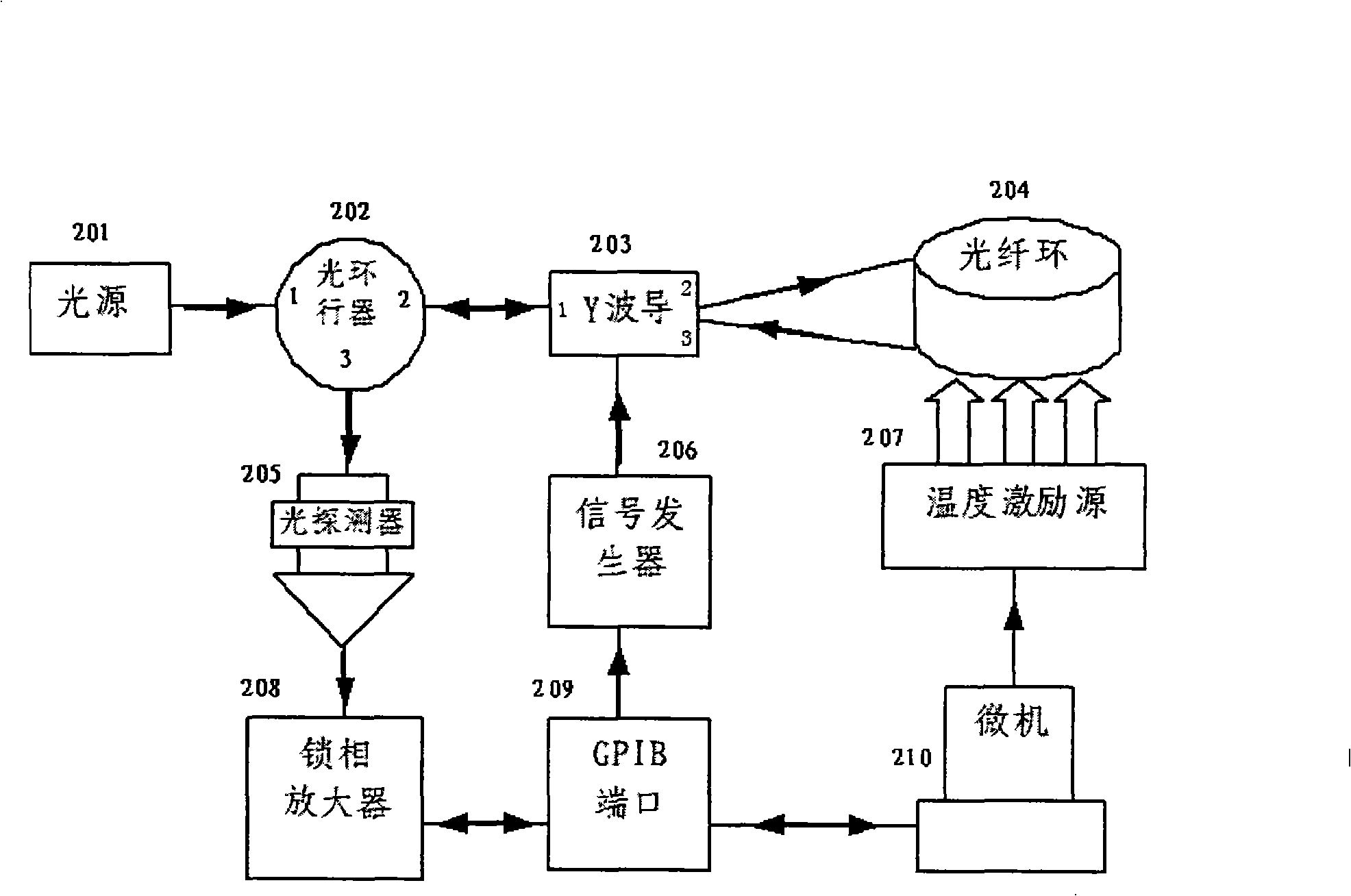
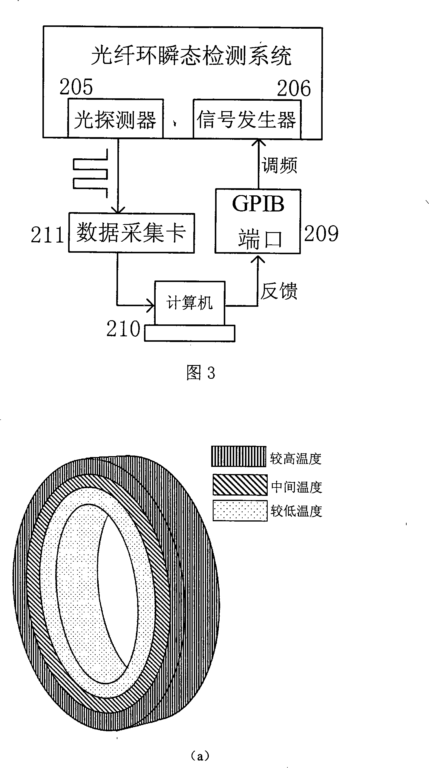
[0065] The basic principle of the present invention is to connect a fiber optic ring to be tested to the fiber optic gyroscope system, and obtain a relationship between the rotation and output of the gyroscope by measuring the signal output at different rotational angular velocities. This relationship can be obtained through a mathematical relationship expression (the present invention establishes a three-dimensional mathematical model for this purpose; using this mathematical relational expression, the rotation of the optical fiber ring can be known more intuitively and accurately by measuring the output of the optical fiber ring). Then put the optical fiber ring in a static state, and perform temperature excitation on it. If the winding symmetry of the optical fiber ring is not good, there will be a signal output corresponding to the rotation. At this time, substitute the output value of such a signal into the previously obtained relational formula, you can Inversely calculat...


PUM


Abstract

The invention relates to a measuring method of the quality of optical fiber ring, used in an optical fiber gyroscope, and a and measuring device thereof; the measuring method and the measuring device belong to the technological field of optical measurement and optical fiber sensing. The method includes the following steps: exerting radial and axial temperature excitation on the optical fiber ring (constant power heating, periodic power heating or non-periodic power heating); measuring the characteristics of the transient temperature of the optical fiber ring; acquiring the test signals of the characteristics of the transient temperature of the optical fiber ring; analyzing and processing the collected data according to the numerical value simulation result of three-dimensional mathematical model of the optical fiber ring; and acquiring the equivalent but asymmetric information of the quantized optical fiber ring which is wound in the radial and axial directions. The device comprises a measuring light source, an optical device which has three ports, a Y wave guide, an optical detector, a signal generator, an electric signal amplification circuit, a controllable heating device, a control circuit and a set of controlling and calculating software. The measuring method can accurately, conveniently and rapidly measure the quality of temperature symmetry of the optical fiber ring, but also can determine the dynamic characteristics of the optical fiber ring without installing the finished product of the optical fiber gyroscope. Thus the measuring method is conducive to the mass production and measurement of the optical fiber ring.

Description

technical field [0001] The invention belongs to the technical fields of optical measurement and optical fiber sensing; in particular, it relates to a detection device and method for detecting the quality of an optical fiber ring used by an optical fiber sensor (also known as an optical fiber gyroscope) for detecting angle changes by utilizing temperature transient changes. Background technique [0002] The fiber optic ring is the sensing core of the fiber optic angle sensor (also known as the fiber optic gyroscope), and its winding quality directly determines the accuracy of the fiber optic gyroscope. At present, traditional fiber ring detection methods (such as judging the quality of polarization-maintaining fiber rings by extinction ratio) cannot fully reflect the winding quality of fiber rings and have limitations. [0003] Fiber optic gyro (Fiber Optic Gyro, FOG) is based on the Sagnac effect, that is, when the ring interferometer rotates, a phase difference proportional...

Claims


Application Information

Patent Timeline
IPC IPC(8): G01M11/02
Inventor 姚晓天李茂春
Owner 苏州光环科技有限公司
Why Eureka
Try Eureka