Flat belt driven dish type splitter

A disc separator and flat belt technology, applied in centrifuges and other directions, can solve the problems of decreased stability and reliability of the whole machine, multiple manufacturing technical requirements for parts, and concentrated latex mixed with gel, etc., and achieve continuous working time. The effect of prolonging, reducing processing technology requirements, and beautiful appearance

Inactive Publication Date: 2009-01-14
薛晓宁
View PDF0 Cites 27 Cited by
  • Summary
  • Abstract
  • Description
  • Claims
  • Application Information

AI Technical Summary

Problems solved by technology

The motor of the existing separator drives the vertical shaft through the horizontal shaft system. The horizontal shaft system includes a centrifugal friction clutch composed of a series of parts such as a connecting wheel, a connector wheel, a friction drum and a friction block. The helical gear transmission includes copper on the horizontal shaft. The gear and the small helical gear on the vertical shaft have nearly 50 parts in total. The structure of the whole transmission system is complex, the transmission line is long, the parts are many and the manufacturing technology requirements are high, which increases the manufacturing cost of the whole machine, and In use, many components such as copper gears, small helical gears, friction drums, friction plates, friction blocks, and connector wheels are vulnerable parts, which require frequent maintenance and replacement, which is troublesome and time-consuming, resulting in a decrease in the stability and reliability of the whole machine. , the accessories are expensive, resulting in high cost of the whole machine
[0003] The drum of the existing latex separator has the following deficiencies: the continuous working time of the drum is short after each shutdown and cleaning, which affects the improvement of productivity, increases the labor intensity, and also affects the separation effect; the key parts of the drum The structure of the drum also needs to be improved in terms of strength, safety and reliability, and maintenance process; the heating phenomenon of the drum causes the gel to be mixed in the concentrated latex, which affects the quality of the latex

Method used


Image

  • Flat belt driven dish type splitter
  • Flat belt driven dish type splitter
  • Flat belt driven dish type splitter

Examples


Embodiment 1

[0072] Latex Disc Separator with Drive / Electric Drive Gear Pump Oil Supply Lubrication

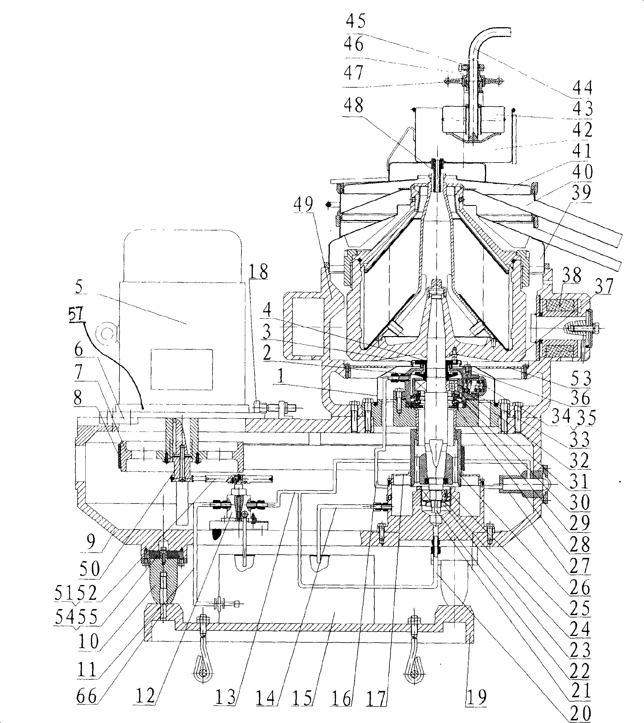
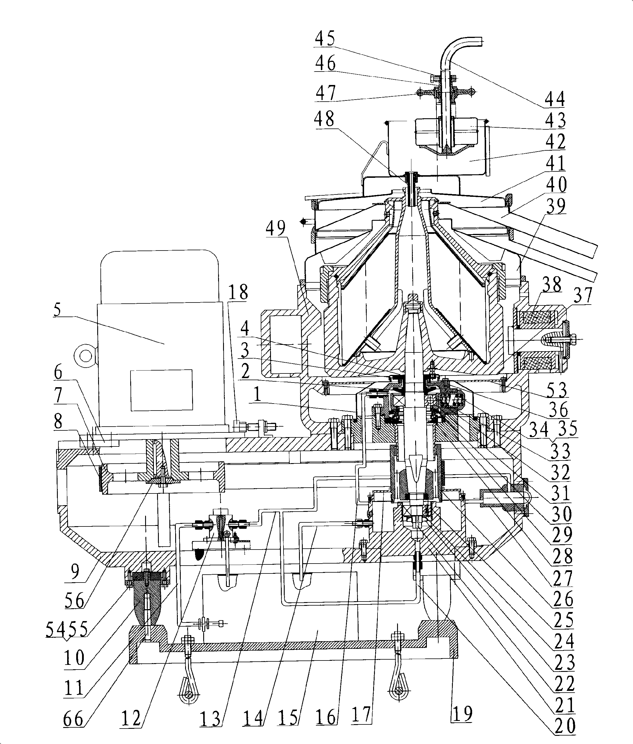
[0073] Such as figure 1 , figure 2 As shown, it is a latex separator for concentrating and separating natural rubber latex, and the disc is provided with a neutral hole. The latex raw material enters the high-speed rotating drum through the feeding pipe and the adjusting barrel, and the raw material is separated into concentrated latex (light phase) and latex (heavy phase) that meet the requirements of relevant standards, and is thrown out of the drum, and separated into the upper collector and output after being combined with the lower collector. Improvements to existing drum technology are as follows:

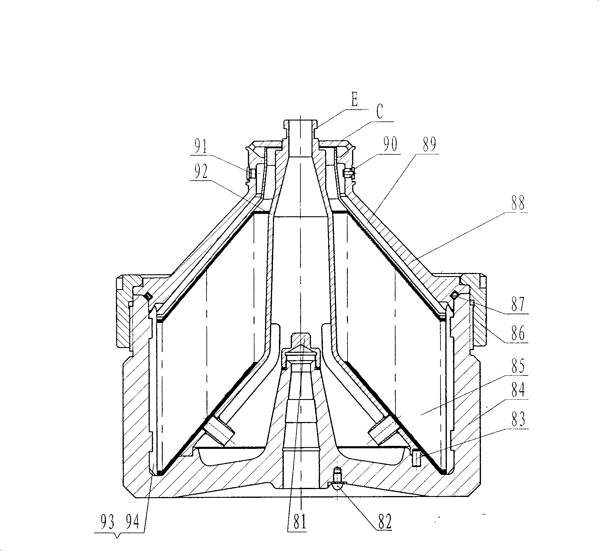
[0074] ①Increased slag holding space: After the drum of the latex separator has been running for a period of time, a ring-shaped gel ring will be formed in the lower cone surface of the feed horn 92, and it will gradually increase with the prolongation of the working time, so that It...

Embodiment 2

[0080] Belt drive / electric drive oil supply lubrication open manual slag discharge disc separator

[0081] Such as figure 1 , figure 2Shown, complete machine is by motor 5, flat belt drive (7,8,26), vertical shaft system and belt radial pressure axial force compensator (1~4,21~26,28~36), by small pulley 50, Large pulley 51, belt 52, oil inlet pipe 11, gear oil pump 12, upper oil inlet pipe 13, oil return pipe 14, oil tank 15, upper bearing oil inlet pipe 16, oil seal cover 17, lower bearing oil inlet pipe 20, oil mirror 27 constitute a lubrication system, Belt tensioning device 18, drum 37, feeding and discharging system (39-48), electromagnetic brake 38, wind gathering plate 53, base 19, outrigger 10, shock absorbing device (54, 55), lower body 9, upper Fuselage 49, frequency converter and electric control cabinet etc. are formed. The motor 5 is started by frequency conversion, which can ensure stable speed-up in the starting process and avoid excessive starting current. ...

Embodiment 3

[0085] Semi-enclosed artificial slag discharge disc separator

[0086] like Figure 8 As shown, the composition includes: motor 5, flat belt transmission (7, 8, 26), vertical shaft system and belt radial pressure axis force compensation device (1 ~ 4, 21 ~ 26, 28 ~ 36), small pulley 50, large Pulley 51, belt 52, oil inlet pipe 11, gear oil pump 12, upper oil inlet pipe 13, oil return pipe 14, oil tank 15, upper bearing oil inlet pipe 16, oil seal cover 17, lower bearing oil inlet pipe 20, oil mirror 27 constitute a lubrication system, and the belt Tensioning device 18, machine base 19, support leg 10, damping device (54,55), lower fuselage 9, light liquid centripetal pump 61, heavy liquid centripetal pump 62, rotating drum 59, upper casing 60, Bottom cover 58, inlet and outlet joint 63, liquid inlet pipe 66, heavy liquid output pipe 64, heavy liquid pressure adjustment device 65, light liquid output pipe 68, light liquid pressure adjustment device 67, inlet and outlet joint c...


PUM


Abstract

The present invention discloses a flat-belt driven disc separator, comprising a power part, a driving part, a lubrication system, a working part, a machine part and a control and assisting part. In addition to that the requirements of the function and performance of the separator is satisfied, the driving system is largely simplified, the driving path is brief, the quantity of driving components is largely reduced and the technical requirement of processing is lowered; regular replacement of expensive copper gear wheel, friction drum and other wearing parts is avoided, and as a result, the structure of the complete machine is simplified, the cost of production and use is reduced, the failure rate of the machine is lowered, and the technical performance of the complete machine is improved. The invention can be directly applied to condensing separation of natural rubber, and the invention can also be applied to separating other emulsions; the rotary-drum structure of the invention can overcome the disadvantages of the prior art; the continuous operation time is prolonged and the rotary-drum heating is alleviated; the strength, safety, reliability and maintenance technique are improved. The driving part and the lower machine body can form the driving of a manual slag-discharge separator, a gushing slag-discharge separator and a ring-valve slag-discharge separator and the lower machine body.

Description

technical field [0001] The patent of the present invention belongs to separation mechanical equipment, in particular to a flat belt drive disc type separator. Background technique [0002] The transmission system of the existing disc separator, especially the latex separator, is composed of centrifugal friction clutch, horizontal shaft system and vertical shaft system. The friction clutch is directly connected with the horizontal horizontal shaft to drive the horizontal shaft and the The copper gear rotates, which drives the small helical gear installed on the vertical shaft perpendicular to the horizontal axis to rotate, driving the vertical shaft and the drum to rotate at high speed. The copper gear and the small helical gear form a helical gear pair. The copper gear is made of special bronze material. . The motor of the existing separator drives the vertical shaft through the horizontal shaft system. The horizontal shaft system includes a centrifugal friction clutch comp...

Claims


Application Information

Patent Timeline
Patent Type & Authority Applications(China)
IPC IPC(8): B04B5/04B04B9/08B04B7/08B04B15/00B04B15/02B04B11/00
Inventor 薛晓宁
Owner 薛晓宁
Why Eureka
Try Eureka