Temperature-measuring device, and method for measuring temperature
A technique for temperature determination, areal density, used in measuring devices, thermometers, thermometers with physical/chemical changes, etc.
- Summary
- Abstract
- Description
- Claims
- Application Information
AI Technical Summary
Problems solved by technology
Method used
Image
Examples
Embodiment 1
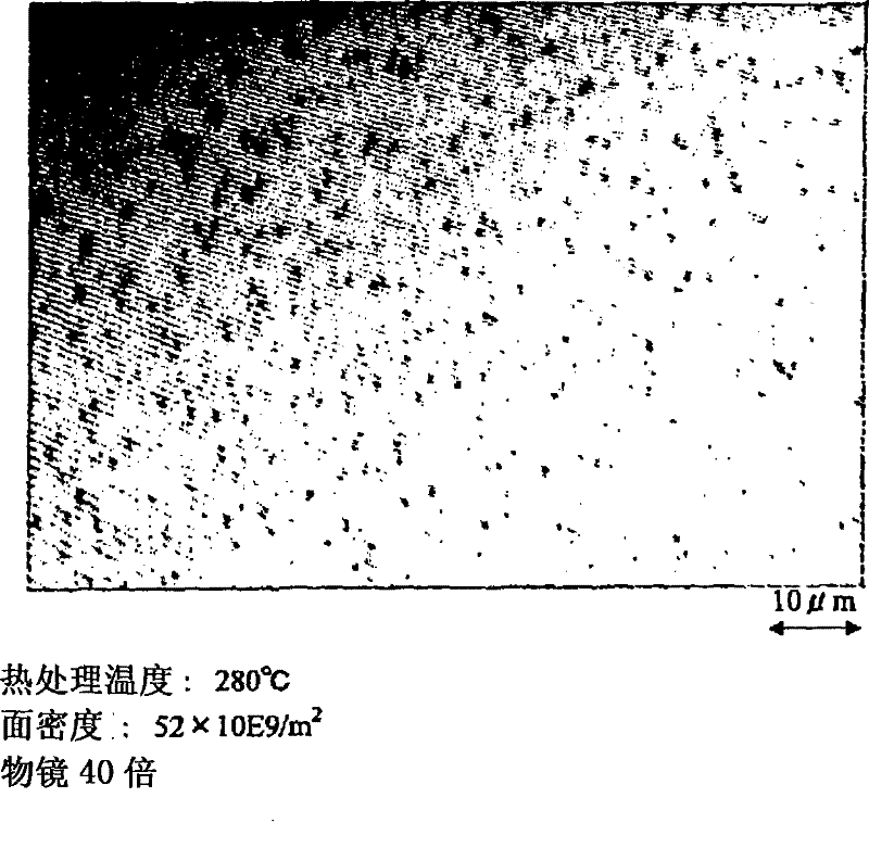
[0142] Through the sputtering method, the vacuum degree is 1.2×10 -6 Torr, the distance between substrate targets is 100mm, the argon gas pressure in the film formation is 2mTorr, and the film formation power is 2W / cm 2 Under the conditions of 0.35 mm thick and 2 inches thick, an aluminum thin film with a film thickness of 300 nm and a purity of 99.99 is formed to form a substrate with a metal thin film. Using this metal thin film-attached substrate, it was heated in an argon atmosphere at a temperature increase of 5° C. / min. The surface shape of the protrusions formed on the surface of the metal thin film of the heated metal thin film substrate was observed with a microscope, and the surface shape was processed by a CCD camera constituting the surface information collecting unit to obtain an analog image signal. This image signal is digitized by an IO board serving as an AD converter to obtain image data. Next, the image data is binarized using the number calculation unit, ...
Embodiment 2
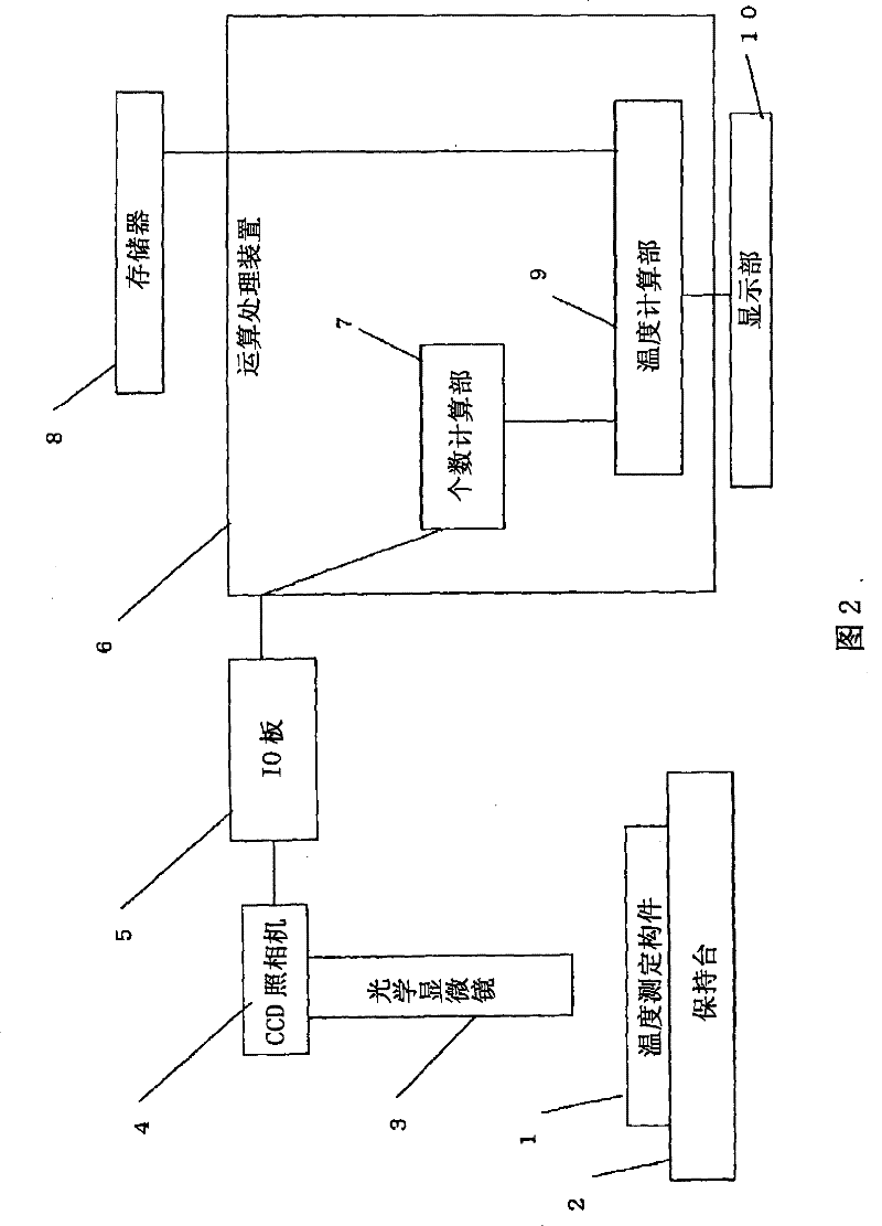
[0148] Hereinafter, the temperature measuring device and the temperature measuring method of the highest attained temperature briefly described in Example 1 will be described. figure 2 It is a block diagram for explaining the temperature measuring device in this embodiment.
[0149] exist figure 2 Among them, 1 is the temperature measuring member that is set in the vacuum heat treatment furnace and given the heat history as the temperature measuring member that should be measured as the target shown in Example 1. An optical microscope for observing the shape of protrusions on the surface of the metal film, 4 is installed on the optical microscope 3, a CCD camera for outputting analog image signals, and 5 is an IO that digitizes the output signal of the CCD camera 4 and is used for outputting image data Board, 6 is the arithmetic processing device connected with the IO board, and 7 is to carry out the binarization process on the digitized image data input from the IO board 5...
Embodiment 3
[0152] Through the sputtering method, the vacuum degree is 1.2×10 -6 Torr, the distance between substrate targets is 100mm, the argon gas pressure in the film formation is 3mTorr, and the film formation power is 2.8W / cm 2 Under the conditions of 0.625 mm thick and 6 inches of silicon wafers, an aluminum thin film with a film thickness of 300 nm and a purity of 99.99 is formed to form a substrate with a metal thin film.
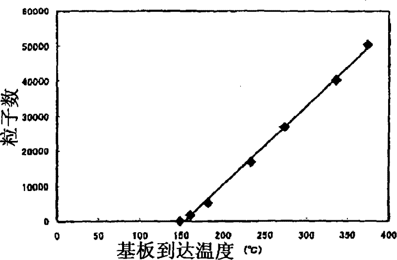
[0153] Next, heat treatment is performed on the above-mentioned substrate with the metal thin film in a vacuum heat treatment furnace. At this time, the temperature increase rate was 5° C. / minute, and after raising to a predetermined temperature, the temperature was maintained for 10 minutes, and then naturally cooled. At this time, a temperature measuring wafer with a thermocouple manufactured by Sensory Co., Ltd. was used to measure the temperature of the central portion of the substrate with the metal thin film, and record the highest attained temperature....
PUM
| Property | Measurement | Unit |
|---|---|---|
| surface roughness | aaaaa | aaaaa |
| surface roughness | aaaaa | aaaaa |
| thickness | aaaaa | aaaaa |
Abstract
Description
Claims
Application Information
 - R&D
- Intellectual Property
- Life Sciences
- Materials
- Tech Scout
- Unparalleled Data Quality
- Higher Quality Content
- 60% Fewer Hallucinations
Browse by: Latest US Patents, China's latest patents, Technical Efficacy Thesaurus, Application Domain, Technology Topic, Popular Technical Reports.
© 2025 PatSnap. All rights reserved.Legal|Privacy policy|Modern Slavery Act Transparency Statement|Sitemap|About US| Contact US: help@patsnap.com


