

Battery
A battery and electrolyte technology, applied in battery electrodes, secondary batteries, circuits, etc., can solve problems such as reducing cycle characteristics, and achieve the effect of improving cycle characteristics and high capacity
- Summary
- Abstract
- Description
- Claims
- Application Information
AI Technical Summary
Problems solved by technology
Method used
Image

Examples
no. 1 example
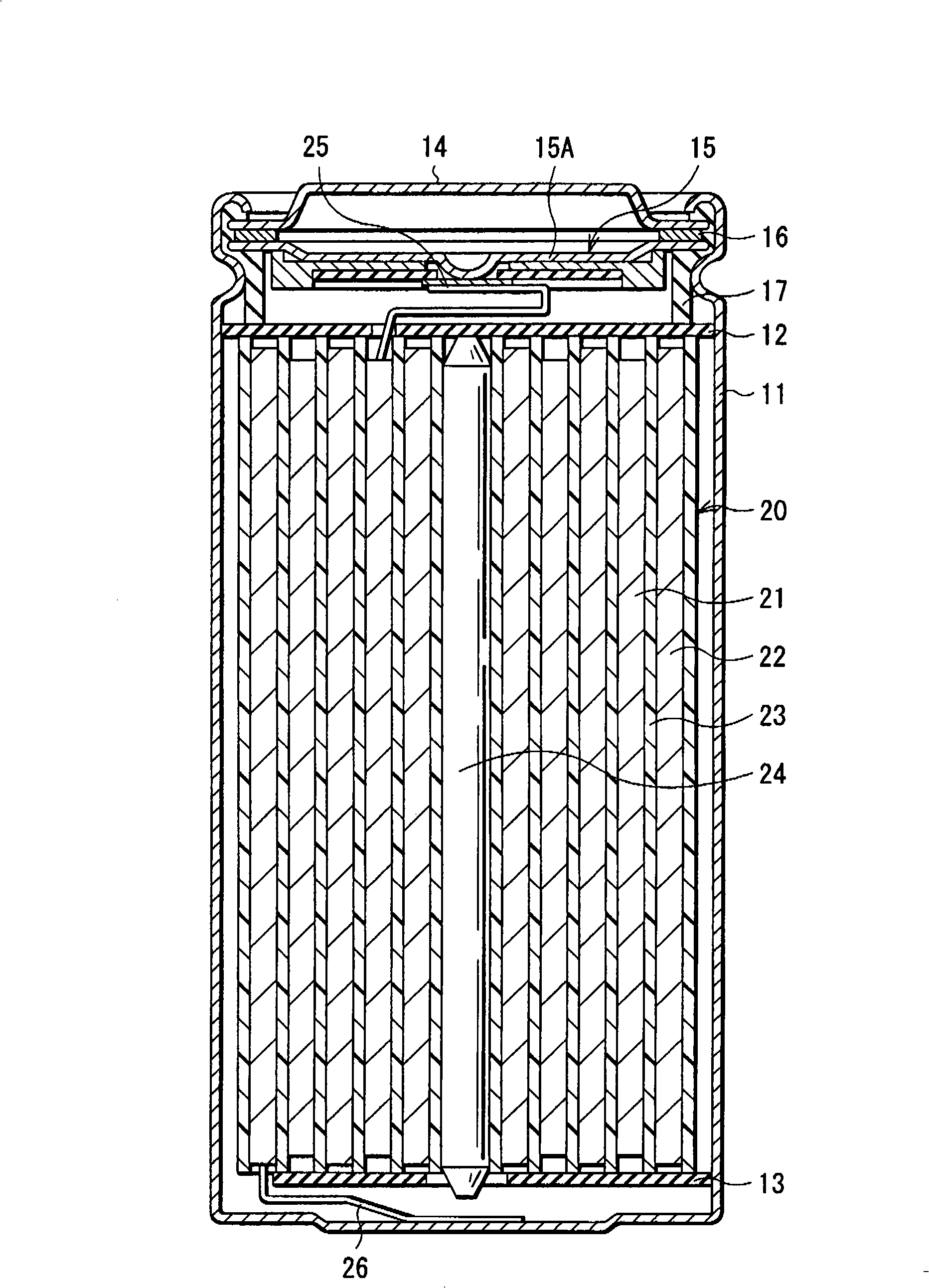
[0030] figure 1 A cross-sectional structure of a battery according to a first embodiment of the present invention is shown. This battery is a lithium ion secondary battery in which the negative electrode capacity is expressed based on intercalation and deintercalation of lithium as an electrode reactant.
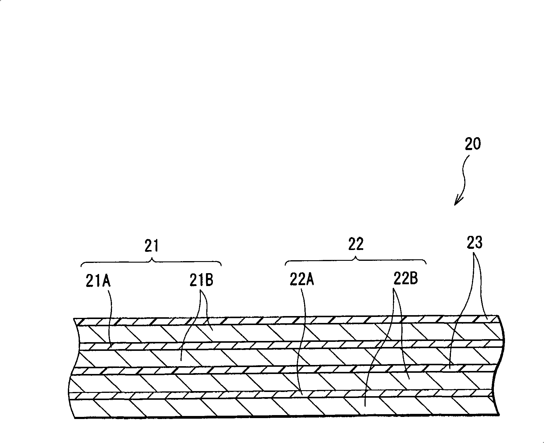
[0031] In this secondary battery, a spirally wound electrode body 20 in which a positive electrode 21 and a negative electrode 22 are laminated with a separator 23 in between and spirally wound, and a pair of insulating plates 12 and 13 are accommodated in an approximately hollow cylindrical shape. Inside the battery case 11. The battery case 11 is made of, for example, nickel-plated iron. One end of the battery case 11 is closed, and the other end thereof is opened. A pair of insulating plates 12 and 13 are arranged perpendicularly to the winding peripheral face, respectively, so that the spirally wound electrode body 20 is sandwiched between the insulating plates 12 and...
no. 2 example
[0095] Hereinafter, a second embodiment of the present invention will be described.
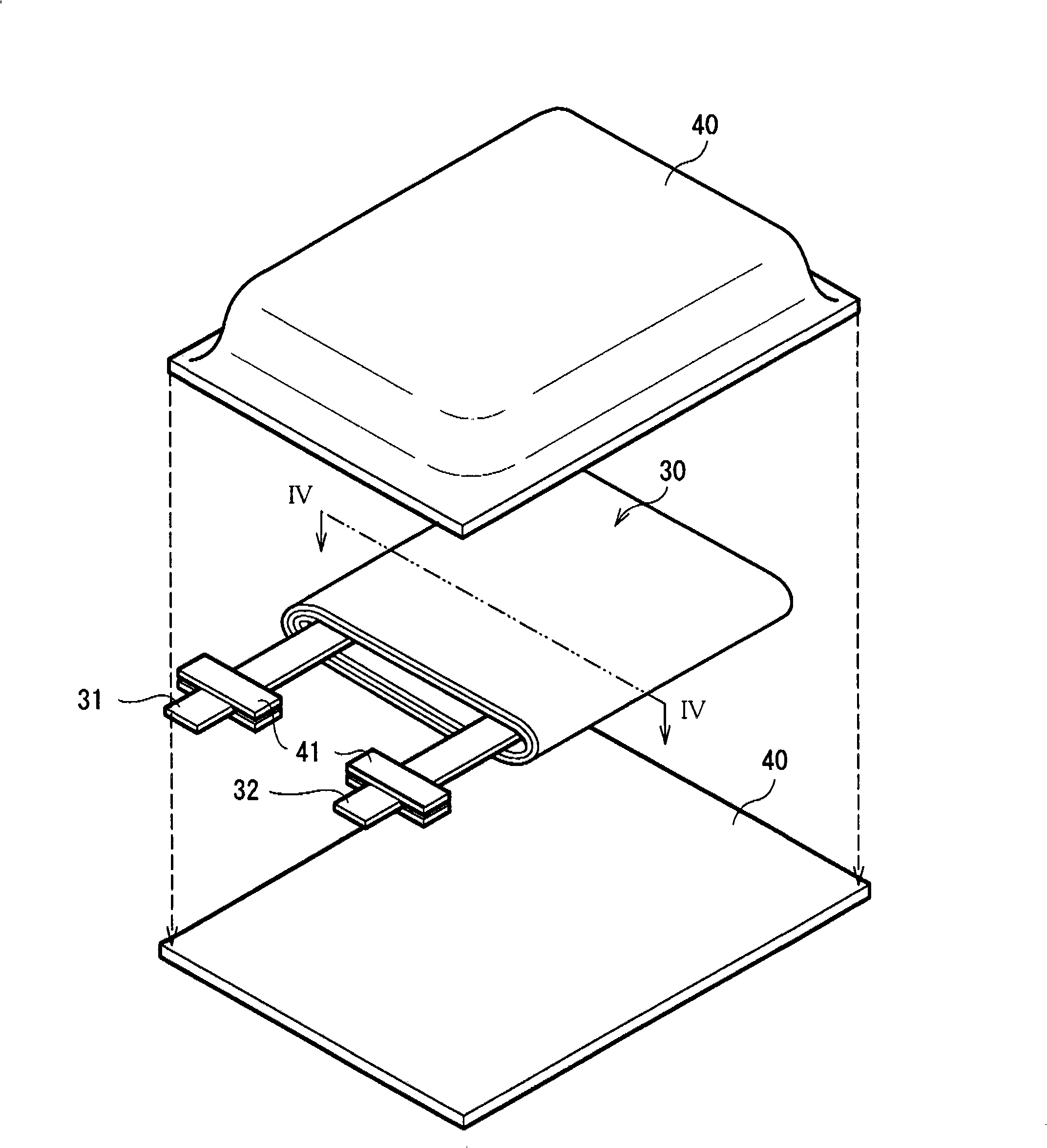
[0096] image 3 An exploded perspective structure of the battery of this embodiment is shown. In this battery, a spirally wound electrode body 30 to which a positive electrode lead 31 and a negative electrode lead 32 are connected is housed in a film package 40 . The battery is a so-called laminate type secondary battery.
[0097] The cathode lead 31 and the anode lead 32 are drawn out in the same direction, for example, from the inside to the outside of the package 40 . The cathode lead 31 is made of, for example, a metal material such as aluminum, and the anode lead 32 is made of, for example, a metal material such as copper, nickel, and stainless steel. The metal material is in the form of a thin plate or a mesh.
[0098] The package 40 is made of a rectangular aluminum laminated film in which, for example, a nylon film, an aluminum foil, and a polyethylene film are bonded together in ...
example 1-1
[0128] As a representative of the above battery, manufactured by the third manufacturing method in the second example image 3 and Figure 4 The laminated film type secondary battery shown. A secondary battery is produced as a lithium ion secondary battery in which the capacity of the negative electrode 34 is expressed based on intercalation and deintercalation of lithium.
[0129] First, the positive electrode 33 is formed. First, 94 parts by weight of lithium cobalt composite oxide (LiCoO 2 ), 3 parts by weight of graphite as a conductive agent, and 3 parts by weight of polyvinylidene fluoride as a binder were mixed to obtain a positive electrode mixture. Then, the cathode mixture was dispersed into N-methyl-2-pyrrolidone to obtain a paste cathode mixture slurry. Subsequently, both surfaces of a positive electrode current collector 33A made of aluminum foil (thickness: 10 μm) were uniformly coated with the positive electrode mixture slurry and allowed to dry. After that...
PUM
| Property | Measurement | Unit |
|---|---|---|
| Thickness | aaaaa | aaaaa |
| Density | aaaaa | aaaaa |
| Thickness | aaaaa | aaaaa |
Abstract
Description
Claims
Application Information