Flue gas catalytic oxidation denitration technique and catalyst thereof

A catalytic oxidation and catalyst technology, which is applied in the fields of coal combustion, flue gas catalytic oxidation and denitrification process and its catalyst, oil-fired boilers and industrial furnaces, to achieve the effect of low cost and high efficiency

Active Publication Date: 2009-01-28
ZHEJIANG TIANLAN ENVIRONMENTAL PROTECTION TECH
View PDF4 Cites 64 Cited by
  • Summary
  • Abstract
  • Description
  • Claims
  • Application Information

AI Technical Summary

Problems solved by technology

Although this method obtains a high NO conversion rate, due to the presence of a large concentration of SO in the flue gas of the coal-fired boiler 2 , at high concentrations of SO 2 The activity of the catalyst under the existing conditions is the key to determine whether the process can be used for denitrification of coal-fired flue gas

Method used


Image

  • Flue gas catalytic oxidation denitration technique and catalyst thereof
  • Flue gas catalytic oxidation denitration technique and catalyst thereof

Examples


Embodiment 1

[0025] 1) Preparation of catalyst CoO by sol-gel method x / TiO 2

[0026] Using n-butyl titanate, ethanol, water, and acetic acid as raw materials, the volume ratio of each component is as follows, n-butyl titanate: ethanol: water: acetic acid = 1: 1.5: 0.5: 0.5, and the amount of cobalt nitrate added is Co : Ti (molar ratio) = 0.1, mixed, after the sol is transformed into a gel, dried, ground, and calcined at 500° C. to obtain a catalyst.

[0027] 2) Denitrification process

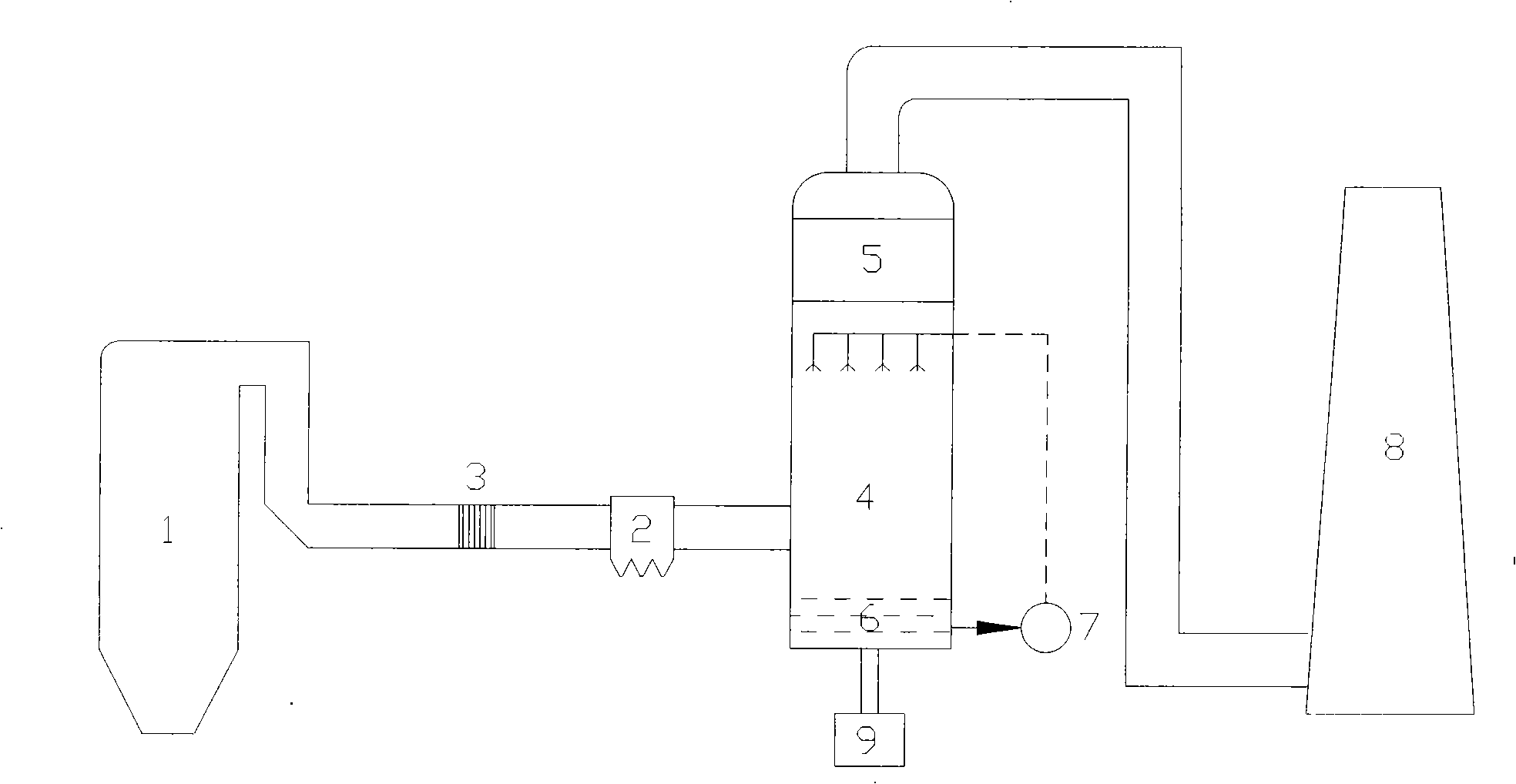
[0028] Treat flue gas O 2 Concentration 3%, GHSV (gas space velocity per hour) = 30000h -1 , the catalytic reactor is installed upstream of the dedusting device, the reaction temperature is 300°C, and the reactor outlet is NO 2 / (NO+NO 2 ) ratio of about 40%-60%, the oxidized flue gas enters the spray tower, and the SO 2 with NO x Remove together, the desulfurization efficiency is 90%, and the denitrification efficiency is 75%.

Embodiment 2

[0030] 1) Preparation of catalyst CoO by impregnation method x / TiO 2

[0031] Cobalt nitrate was added to commercial titanium dioxide slurry, stirred for 48 hours, dried at 100°C, calcined at 500°C for 2 hours, and ground to obtain a catalyst. The amount of cobalt added is Co:Ti (molar ratio)=0.05.

[0032] 2) Denitrification process

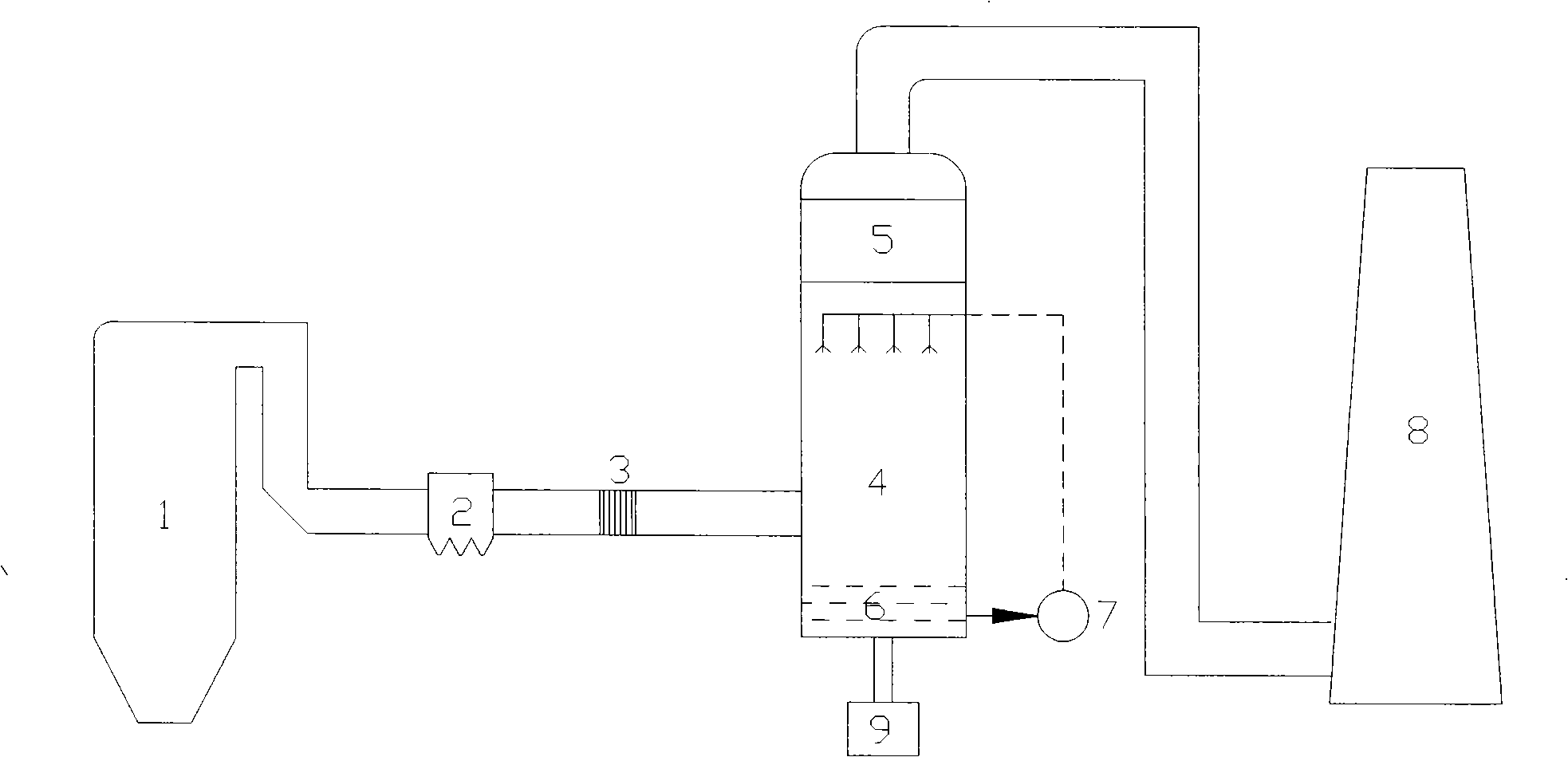
[0033] Treat flue gas O 2 Concentration 5%, GHSV (gas space velocity per hour) = 50000h -1 , the catalytic reactor is installed upstream of the dedusting device, the reaction temperature is 350°C, and the reactor outlet is NO2 / (NO+NO 2 ) ratio of about 40%-60%, the oxidized flue gas enters the packed tower, and the SO 2 with NO x Remove together, the desulfurization efficiency is 95%, and the denitrification efficiency is 80%.

Embodiment 3

[0035] 1) Preparation of catalyst CoO by sol-gel method x / ZrO 2 -TiO 2

[0036] Using n-butyl titanate, ethanol, water, and acetic acid as raw materials, the volume ratio of each component is as follows, n-butyl titanate: ethanol: water: acetic acid = 1: 1.65: 0.05: 0.07, and the amount of cobalt nitrate added is Co : Ti=0.05, the addition of zirconium nitrate is Zr:Ti (molar ratio)=0.1, mixed, after the sol is converted into gel, dried, ground, and roasted at 600°C to obtain the catalyst.

[0037] 2) Denitrification process

[0038] Treat flue gas O 2 Concentration 8%, GHSV (gas space velocity per hour) = 40000h -1 , the catalytic reactor is installed downstream of the dedusting device, the reaction temperature is 200°C, and the reactor outlet is NO 2 / (NO+NO 2 ) ratio of about 40%-60%, the oxidized flue gas enters the swirl plate tower, and the SO 2 with NO x Remove together, the desulfurization efficiency is 90%, and the denitrification efficiency is 85%.


PUM


Abstract

The invention provides a smoke catalysis and oxidation denitration process which takes a catalyst using TiO2 or ZrO2-TiO2 as a carrier and Co as active ingredient, uses the oxygen contained in the smoke to oxidate the NO as NO2 which is easy to be dissolved in water, utilizes the alkali solution to absorb the NO2 and remove the NOx. The process of the invention has high denitration efficiency and low cost, can selectively recover the nitrite in the denitration outgrowth and realize the resource utilization of the outcome after controlling the content of the NO2 in the oxidated smoke.

Description

technical field [0001] The invention relates to the technical field of air pollution control, in particular to a flue gas catalytic oxidation denitrification process and a catalyst thereof, which are suitable for coal-fired and oil-fired boilers and industrial furnaces. Background technique [0002] Gas-phase oxidation-absorption denitrification technology uses gas-phase oxidation to reduce flue gas NO x NO with low solubility is oxidized to NO 2 , N 2 o 5 etc., and then absorb it with alkaline, oxidizing or reducing absorbing liquid. The method can not only realize denitrification and purification of waste gas, but also realize resource utilization of nitrogen oxides. The difference between various gas-phase oxidation-absorption denitrification technologies lies in the different gas-phase oxidation methods. Gas-phase oxidation methods can be divided into direct oxidation of gas-phase chemical agents, gas-phase photocatalytic oxidation, and gas-phase catalytic oxidation...

Claims


Application Information

Patent Timeline
Patent Type & Authority Applications(China)
IPC IPC(8): B01D53/56B01D53/86B01J23/75B01J37/03
Inventor 吴忠标盛重义王海强王婕刘越
Owner ZHEJIANG TIANLAN ENVIRONMENTAL PROTECTION TECH
Why Eureka
Try Eureka