Apparatus and method for discharging and degaussing of electromagnetic clutch

An electromagnetic clutch and degaussing device technology, applied in the direction of magnetic drive clutches, clutches, non-mechanical drive clutches, etc., can solve the problems of mechanical failure, coil burnout, coil heat and moisture, etc., to avoid abnormal damage and reduce accidents rate, to ensure the effect of normal operation

Active Publication Date: 2009-01-28
BAOSHAN IRON & STEEL CO LTD
View PDF0 Cites 4 Cited by
  • Summary
  • Abstract
  • Description
  • Claims
  • Application Information

AI Technical Summary

Problems solved by technology

[0003] Since the electromagnetic clutch brush is made of copper, the brush is connected to the clutch coil through frictional contact with the iron clutch ring. The electromagnetic clutch ring rotates at high speed in the gearbox, and the oil film pressure generated by the lubricating oil in the gearbox causes The copper contact of the brush is floating, and the relative spring force is reduced, which is easy to cause poor contact, arc burning of the clutch ring, damage to the clutch ring, and cause the machine to fail to work normally.
At the same time, the frequent use of the electromagnetic clutch results in short intervals and high frequency between disengagement and pull-in of the electromagnetic clutch each time; in addition, because the coil is similar to an inductive element, it is an energy storage element that can store current. , the coil is heated and damp, and the discharge performance becomes poor; after each cycle of the electromagnetic clutch completes a cycle, there will be residual current, which will accumulate repeatedly, resulting in the failure of the clutch coil to discharge and degauss in time, causing the coil to burn out and the electromagnetic clutch to be damaged

Method used


Image

  • Apparatus and method for discharging and degaussing of electromagnetic clutch
  • Apparatus and method for discharging and degaussing of electromagnetic clutch
  • Apparatus and method for discharging and degaussing of electromagnetic clutch

Examples


Embodiment Construction

[0020] The present invention will be further described below in conjunction with the accompanying drawings and specific embodiments.

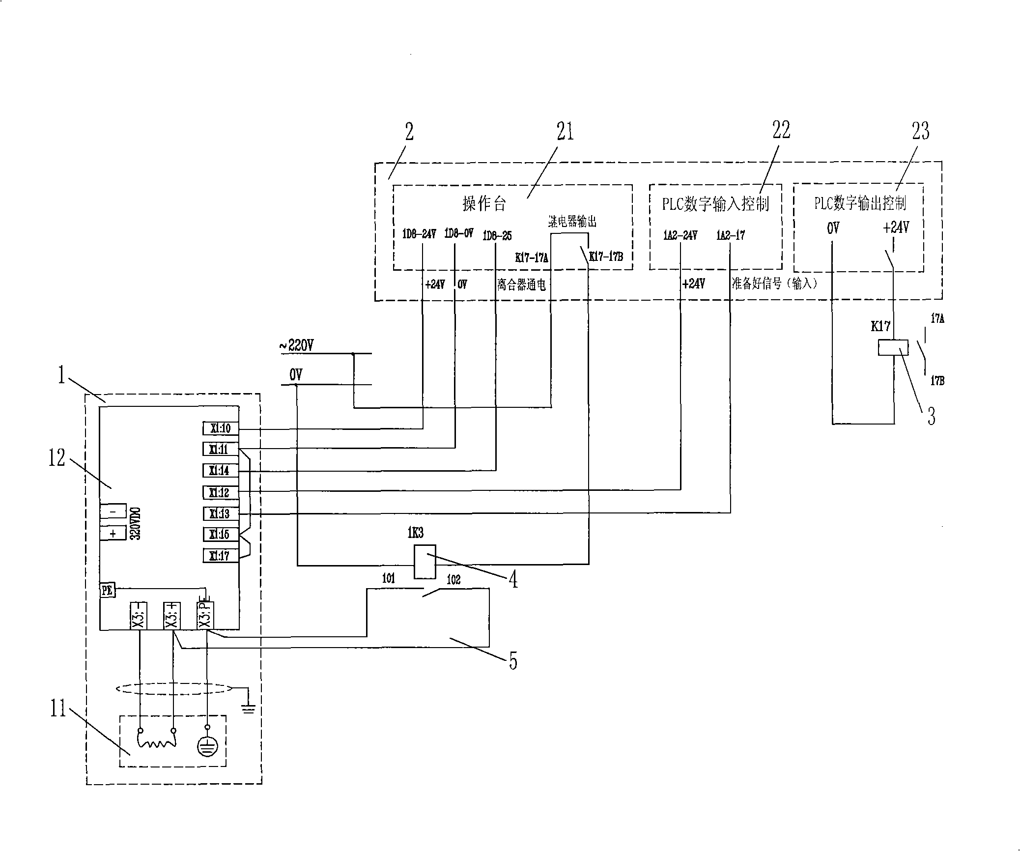
[0021] see figure 1 , an electromagnetic clutch discharge degaussing device, comprising an electromagnetic clutch and its control unit 1, a PLC control unit 2, and a discharge degaussing unit. The electromagnetic clutch and its control unit 1 include an electromagnetic clutch body 11, an electromagnetic clutch amplification control module 12, a rectifier transformer, a low-voltage circuit breaker, and a corresponding working power supply; the PLC control unit 2 includes an operating console 21, a PLC digital input control 22, and a PLC digital output control 23. The discharge degaussing unit includes the intermediate relay 3 and its auxiliary normally open contacts 17A and 17B, the degaussing intermediate relay 4 and its auxiliary normally open contacts 101 and 104. The PLC control unit 2 is connected with the electromagnetic clutch and its co...


PUM


Abstract

The invention discloses a discharging and degaussing device for an electromagnetic clutch and a method thereof. The discharging and degaussing device comprises the electromagnetic clutch and a control unit thereof, a PLC control unit which is connected with the electromagnetic clutch and the control unit of the electromagnetic clutch. The invention is characterized in that: the discharging and degaussing device also comprises an intermediate relay and a degaussing intermediate relay; wherein, the intermediate relay is connected to the digital output control end of the PLC control unit; the auxiliary normal open contact of the intermediate relay is connected to a main circuit of the degaussing intermediate relay; one of the auxiliary normal open contacts of the degaussing intermediate relay is connected with a grounding wire and the other is connected with the coil of the electromagnetic clutch; a discharging and degaussing circuit of the electromagnetic clutch is formed by the connection of the two auxiliary normal open contacts of the degaussing relay with the coil of the electromagnetic clutch and the grounding wire. The device of the invention can discharge and degauss the coil of the clutch, thus reducing the short circuit of the coil and preventing the electromagnetic clutch from abnormal damage.

Description

technical field [0001] The invention relates to a control circuit and a method of an electromagnetic clutch, in particular to an electromagnetic clutch discharge degaussing device and a method. Background technique [0002] A clutch is a mechanical device that transmits the rotational force (torque) or motion of the active side on the coaxial line to the driven side. It can be freely engaged and disengaged according to the needs of the user. It is called an electromagnetic clutch that uses electromagnetic force to act. . The electromagnetic clutch uses the electromagnetic force generated by the magnetic field of the energized excitation coil to manipulate the engaging elements to make the clutch engage or disengage. It has the advantages of large starting torque, fast action response, quick clutch, simple structure, convenient installation and maintenance, long service life, and controllability. Simple, low power and other characteristics, therefore, electromagnetic clutche...

Claims


Application Information

Patent Timeline
Patent Type & Authority Applications(China)
IPC IPC(8): F16D27/00H01F13/00
Inventor 方英赵月根唐伟徐磊
Owner BAOSHAN IRON & STEEL CO LTD
Why Eureka
Try Eureka