Wave straightly-drive type straight-line magneto resistance power generation system

A power generation system and direct drive technology, applied in control systems, ocean energy power generation, electromechanical devices, etc., can solve the problems of poor reliability, high cost and uneconomical, etc., and achieve the effect of avoiding corrosion, low cost and good fault tolerance

Inactive Publication Date: 2009-01-28
XI AN JIAOTONG UNIV
View PDF2 Cites 27 Cited by
  • Summary
  • Abstract
  • Description
  • Claims
  • Application Information

AI Technical Summary

Problems solved by technology

[0005] In order to solve the problems of poor long-term operation reliability, high cost and uneconomical problems existing in existing wave power generation devices, the present invention provides a wave direct drive linear reluctance power generation system, which can simplify the structure of the wave power generation system and volume, save the secondary energy conversion device, improve the efficiency of wave energy generation, and at the same time avoid the corrosion and loss of magnetism of the permanent magnet

Method used


Image

  • Wave straightly-drive type straight-line magneto resistance power generation system
  • Wave straightly-drive type straight-line magneto resistance power generation system
  • Wave straightly-drive type straight-line magneto resistance power generation system

Examples


Embodiment 1

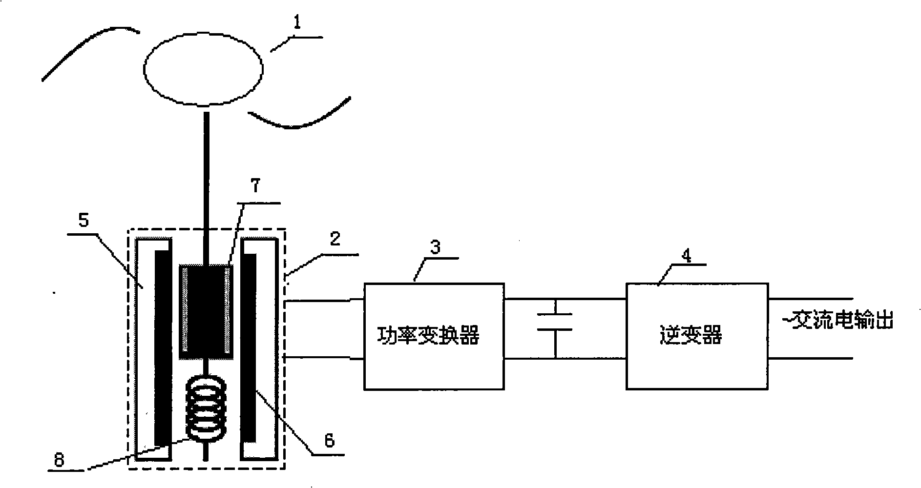
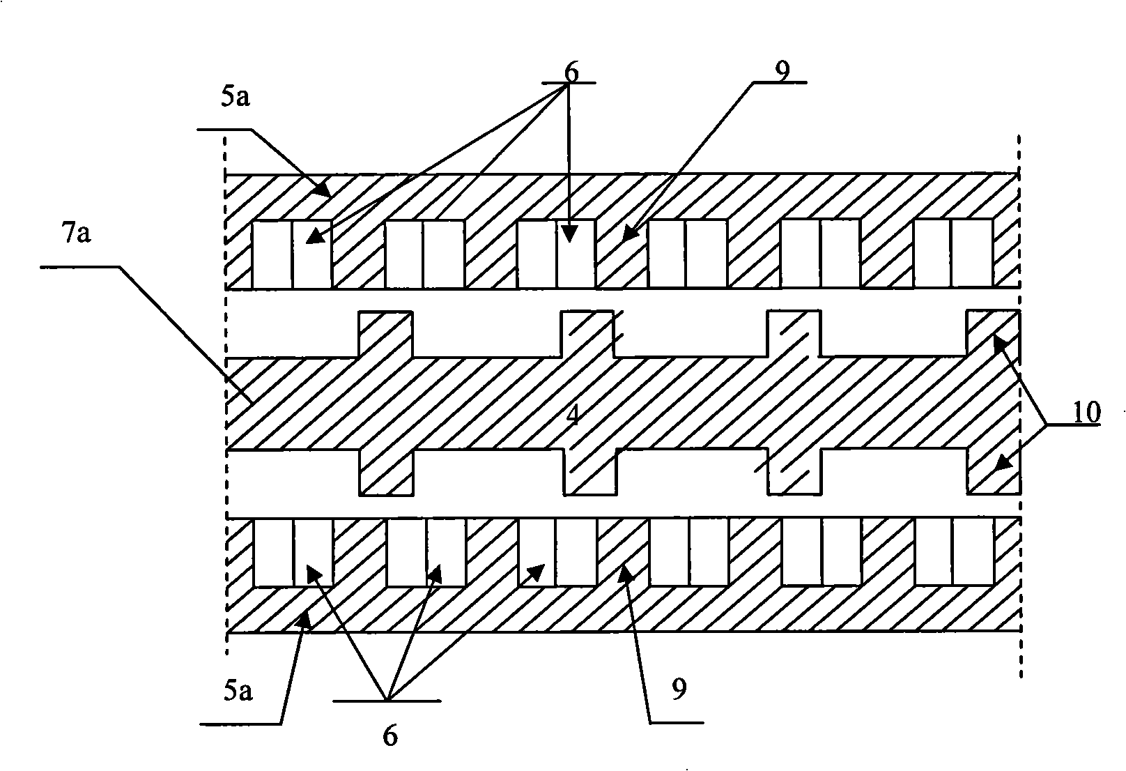
[0016] combine 1, figure 2 and Figure 4 , The wave power generation system of the present invention includes a wave energy absorbing device 1 , a linear switched reluctance generator 2 , a power conversion unit 3 and an inverter unit 4 . The linear switched reluctance generator 2 is composed of an initial pole 5a made of silicon steel sheets, a three-phase winding 6 for the initial pole, and a secondary pole 7a made of silicon steel sheets with tooth grooves. The lower end of the mover 7 is installed on the base of the generator through a spring 8 , and the upper end of the mover 7 is elastically connected with the wave energy absorbing device 1 . The whole power generation system can be installed on the seabed by the container, and the motion of the wave moves up and down with the wave energy absorbing device 1 placed underwater or on the water surface during operation, thereby driving the mover 7 of the linear switched reluctance generator 2 to move up and down. The wave...

Embodiment 2

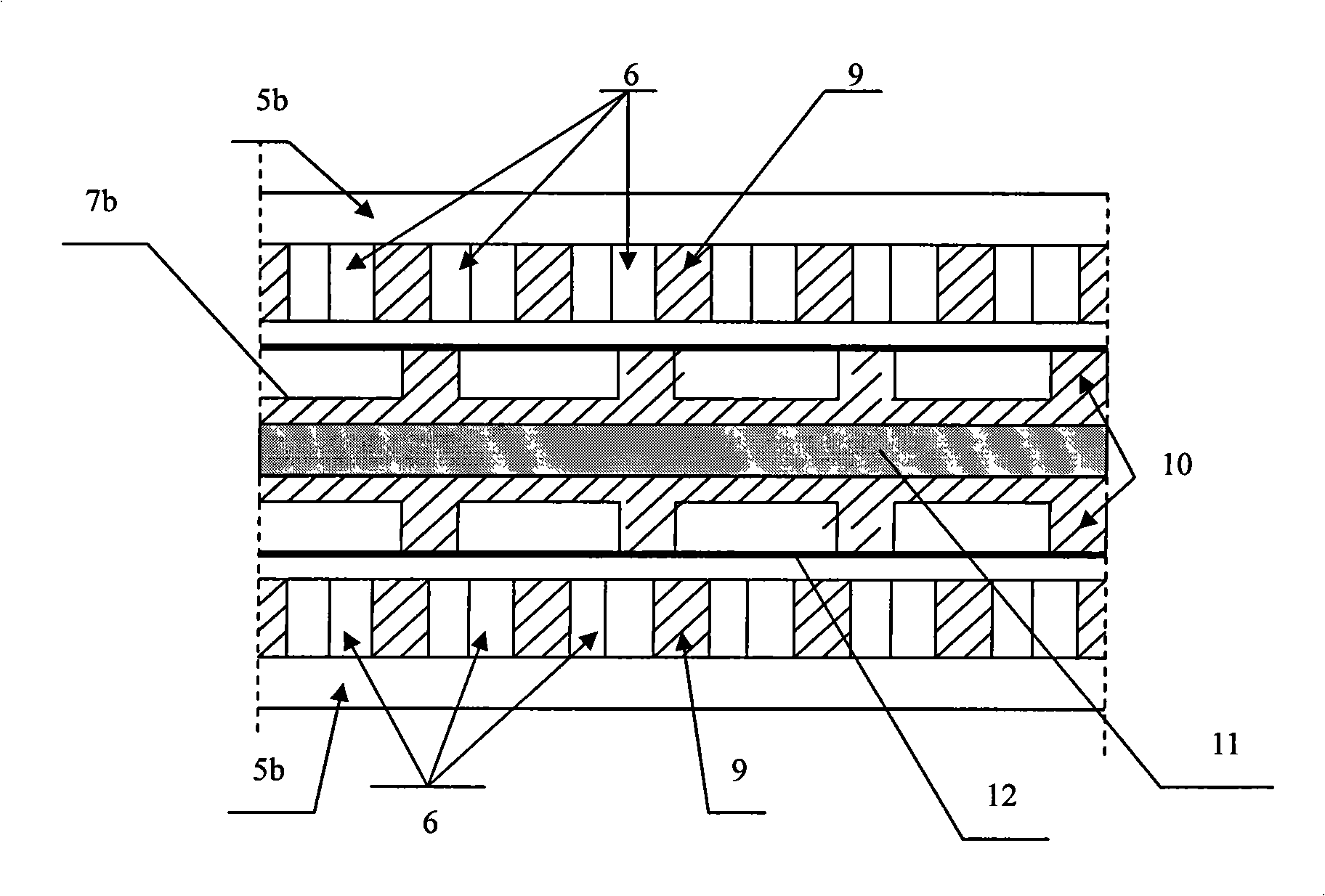
[0018] combine figure 1 , image 3 and Figure 4 , on the basis of Example 1, the figure 2 The double-sided structure of the primary pole iron core and the secondary pole mover shown is replaced by image 3 The cylindrical structure shown. The primary pole iron core lamination of the cylindrical switched reluctance linear motor is a cylindrical iron core 5b, and the primary pole winding 6 is a cake-shaped coil, which are laminated in the cylindrical iron core wiring groove in turn; the secondary pole mover is made of silicon steel The sheets are stacked into an annular iron core 7b with tooth grooves, and are tightly fitted on the outer diameter of a non-magnetic solid metal cylinder 11, and the outer layer is tightened by a non-magnetic metal thin-walled cylinder 12. Compared with the unilateral structure and double-sided structure, the advantage of the cylindrical structure is less magnetic flux leakage and higher efficiency.

[0019] The working principle of the linea...


PUM


Abstract

The invention discloses a wave direct-drive linear reluctance generator system which comprises a generator, a power inverter, and an inverter, wherein the output of a primary three-phase winding of the generator is connected with the input of the power inverter, the output of the power inverter is connected with the inverter, and the output of the inverter is connected with a power grid or a use load. The system is characterized in that the generator is a direct-drive linear switched reluctance generator which comprises a primary iron core embedded with a three-phase winding and a secondary mover which is arranged in the primary iron core and is provided with tooth grooves, the primary iron core and the secondary mover are formed by overlapping silicon sheets, the lower end of the secondary mover is fixed on a generator base through an elastic component, and the upper end of the secondary mover is elastically connected with a wave energy absorbing device. The system replaces a permanent-magnet synchronous linear motor with the linear switched reluctance generator, which saves a secondary energy conversion device, can simplify the structure and the volume of the generator system, improve the efficiency of wave energy power generation, and also avoid problems of corrosion and excitation loss of permanent magnets and so on.

Description

technical field [0001] The invention relates to a wave energy conversion device, in particular to a wave direct-driven linear reluctance power generation system. Background technique [0002] As the main way of wave energy utilization, wave power generation converts wave energy into mechanical energy first and finally into electrical energy through a wave energy conversion device. At present, there are many types of wave energy utilization devices. Summarizing the characteristics of existing wave energy utilization devices, it can be known that existing wave energy utilization devices generally originate from the following basic principles: 1) Utilize the oscillation and swing of objects under the action of waves; 2) ) Utilize the change of wave pressure; 2) Utilize the coastal climb of the wave to convert the wave energy into the potential energy of water. Most of the existing wave power generation devices can be regarded as a system including three levels of energy conver...

Claims


Application Information

Patent Timeline
Patent Type & Authority Applications(China)
IPC IPC(8): H02K29/00H02K1/12H02K1/22H02K3/12H02K3/28H02P6/00F03B13/22
CPCY02E10/38Y02E10/30
Inventor 梁得亮娄建勇李双凤赵东东倪赛赛
Owner XI AN JIAOTONG UNIV
Why Eureka
Try Eureka