
Automatic sprayer and control method thereof

A sprayer, automatic technology, applied in spraying devices, manufacturing tools, casting and molding equipment, etc., can solve the problems of low work efficiency, high price, unable to spray amount and spraying time control and other problems

Inactive Publication Date: 2009-02-04
上海华立电子工程有限公司
View PDF0 Cites 19 Cited by
  • Summary
  • Abstract
  • Description
  • Claims
  • Application Information

AI Technical Summary

Problems solved by technology

[0007] Due to the existence of these problems, the fixed-point control of the spraying position cannot be carried out during work, so that the spraying amount and spraying time required for each position cannot be controlled, and the spraying effect is not good; at the same time, there are also situations of low work efficiency and high cost.
[0008] 2. Existing foreign sprayers
Therefore, the cost is higher and the price is expensive

Method used

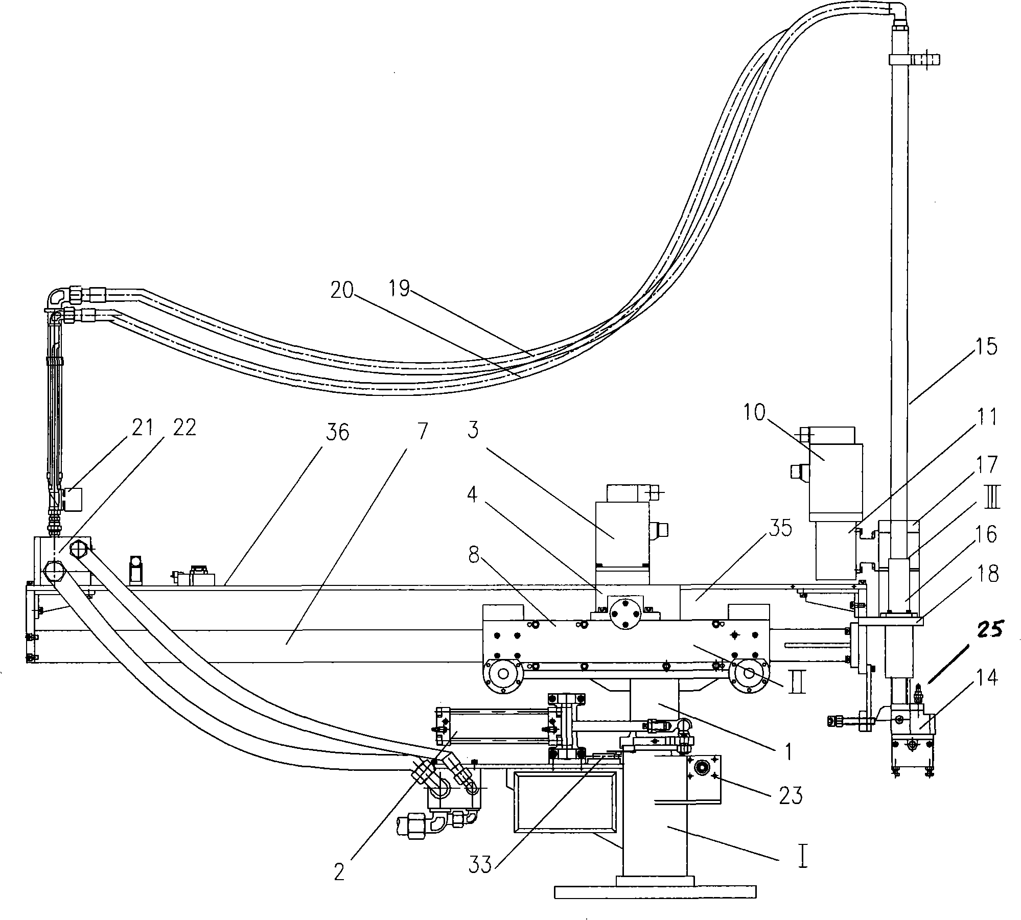

Image

  • Automatic sprayer and control method thereof
  • Automatic sprayer and control method thereof
  • Automatic sprayer and control method thereof

Examples


Embodiment 1

[0187] It will be described in conjunction with FIG. 10 .

[0188] First, the power supply circuit will be described. AC 380V / 50Hz is a three-phase AC power grid with a line voltage of 380 volts, a frequency of 50 Hz, and a phase voltage of 220 volts. U, V, W are the three phase wires, N is the neutral wire, PE is the safety ground wire, and K1 is the main switch of the AC power supply.

[0189] ZL is a direct current power supply, and DC24V is a direct current of 24 volts.

[0190] The 220V AC mains is sent to the input terminal of the DC power supply, and the output terminal of the DC power supply outputs a 24-volt DC power, and the DC power is sent to the signal circuit, control circuit, conversion circuit, executive components, and man-machine interface device through the line.

[0191] Second, the control circuit and its related circuits will be described. In this embodiment, the intelligent controller used by the control circuit is PCL. PCL is a programmable controll...

Embodiment 2

[0198] It will be described with reference to FIG. 11 .

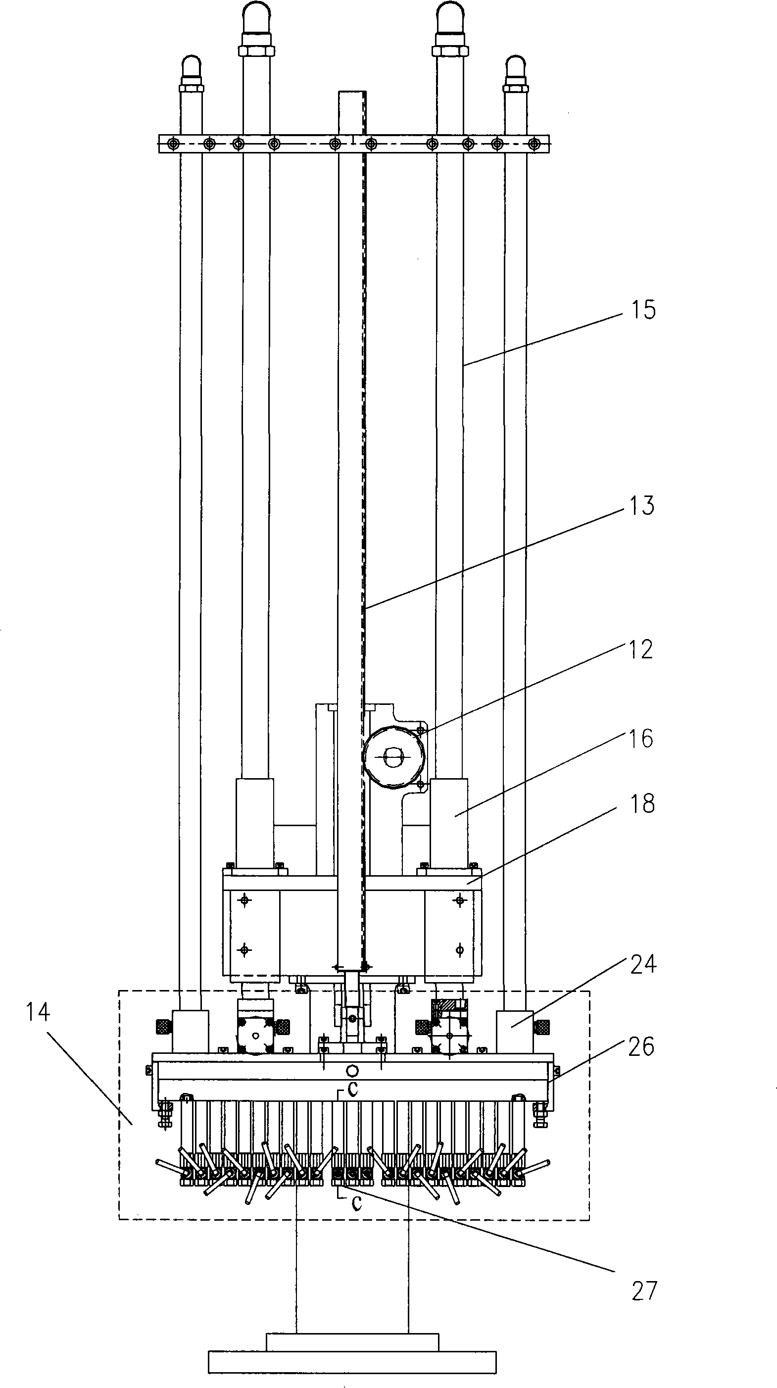
[0199] The labels in the figure will be explained first. 2 is cylinder, 21 is blowing valve, 24 is atomizer, 25 is air control valve, 26 is spray block, 27 is nozzle, DXF is one-way valve, GLQ is filter, JYF-1 is pressure reducing valve, JYF-2 is a pressure reducing valve, JXQ is a shut-off muffler, KYJ is an air compressor, KGQ is an air filter, TDCF is a release agent solenoid valve, RQ is a container, TJF is a water volume adjustment switch, WDCF is an atomization solenoid valve, XZD is a rotary solenoid valve and YLB is a pressure gauge.

[0200] Figure 11 is used to illustrate the basic principle of the gas circuit. When implementing the present invention, the atomizer 24 and various solenoid valves and the like are not limited to two sets, and more can also be used.

Embodiment 3

[0202] combine Figure 12 , Figure 13 , Figure 14 , Figure 15 , Figure 16 , Figure 17 ,Be explained. The above 6 figures are schematic diagrams in the top view direction.

[0203] The labels in the figure will be explained first. 14 is a spraying part; 38 is a static mold in a die-casting mold; 39 is a moving mold in a die-casting mold.

[0204] There are two rows of nozzles on the spraying part 14, one row is dedicated to blowing and spraying the static mold, and the other row is dedicated to blowing and spraying the moving mold.

[0205] Die casting machine mold is divided into two parts: static mold and dynamic mold. When die-casting products, the static mold and the dynamic mold are combined, such as Figure 12 shown. After the die-casting of the product is completed, the static mold does not move and the movable mold moves separately, such as Figure 13 As shown, at this time, the product can be unloaded from the gap between the static mold and the movable...


PUM


Abstract

The present invention discloses an automatic sprayer and an operating method thereof and relates to the technology of a die-casting machine die spray parting agent. The present invention aims at providing a sprayer with low cost and high automatization degree and a control method thereof. In the technical proposal, a device comprises a mechanical part, a circuit part and a gas circuit part; the mechanical part consists of a frame, a horizontal moving mechanism and a vertical moving mechanism; the horizontal moving mechanism is provided with two sets of unique rolling shafts; the vertical moving mechanism is provided with a leader and a linear bearing which respectively replaces a linear guide way with high cost; a spray block is provided with a globe joint adjustable nozzle. The circuit part comprises a power supply circuit, a signal circuit, a control circuit, a conversion circuit, an executive component (OC) and a man-machine interface device. The gas circuit uses an air compressor (KYJ) to produce compressed gas, and the compressed gas and the parting agent are transmitted and distributed by an air pipe and a water pipe. The automatic sprayer has the beneficial effects of simple structure, high efficiency, good spraying effect and being capable of spraying at fixed point and reducing labor intensity.

Description

technical field [0001] The invention relates to the technical field of spraying, in particular to an automatic sprayer for spraying mold release agents for die-casting machines and an operating method thereof. Background technique [0002] Die casting technology is widely used in automobiles, motorcycles, electrical appliances, communications, aviation and other fields. With the continuous improvement of product quality, equipment performance and automation requirements, currently used for supporting die-casting machines: [0003] 1. Domestic existing sprayer [0004] The vertical movement of the sprayer is driven by the cylinder, and the stroke is determined by the stroke of the cylinder itself, which cannot be set according to the needs; the horizontal movement can only be done in advance by manually rotating the hand wheel, or driving the screw rod by an ordinary motor to make the sprayer move horizontally. adjusted to a certain position. [0005] The nozzle adopts a l...

Claims


Application Information

Patent Timeline
Patent Type & Authority Applications(China)
IPC IPC(8): B05B15/00B05B13/02B22C23/02
Inventor 谢立型包贤德
Owner 上海华立电子工程有限公司
Learn More