Ultraviolet irradiation device

A technology for irradiation devices and ultraviolet rays, which is applied in the direction of lighting devices, damage prevention measures for lighting devices, lighting and heating equipment, etc., and can solve problems such as a large amount of nitrogen

Active Publication Date: 2012-07-04
HARISON TOSHIBA LIGHTING CORP
View PDF1 Cites 0 Cited by
  • Summary
  • Abstract
  • Description
  • Claims
  • Application Information

AI Technical Summary

Problems solved by technology

[0004] However, because the existing ultraviolet irradiation device has a structure in which the dielectric barrier discharge lamp is cooled by nitrogen introduced into the lamp housing, in order to light the dielectric barrier discharge lamp for a long time and obtain a stable illuminance, it is necessary to lower the temperature of the lamp. Maintained at a substantially constant temperature, so there is the problem of requiring a large amount of nitrogen

Method used


Image

  • Ultraviolet irradiation device
  • Ultraviolet irradiation device
  • Ultraviolet irradiation device

Examples


no. 1 approach

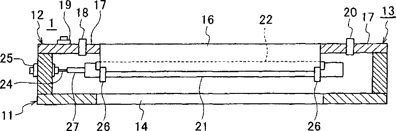
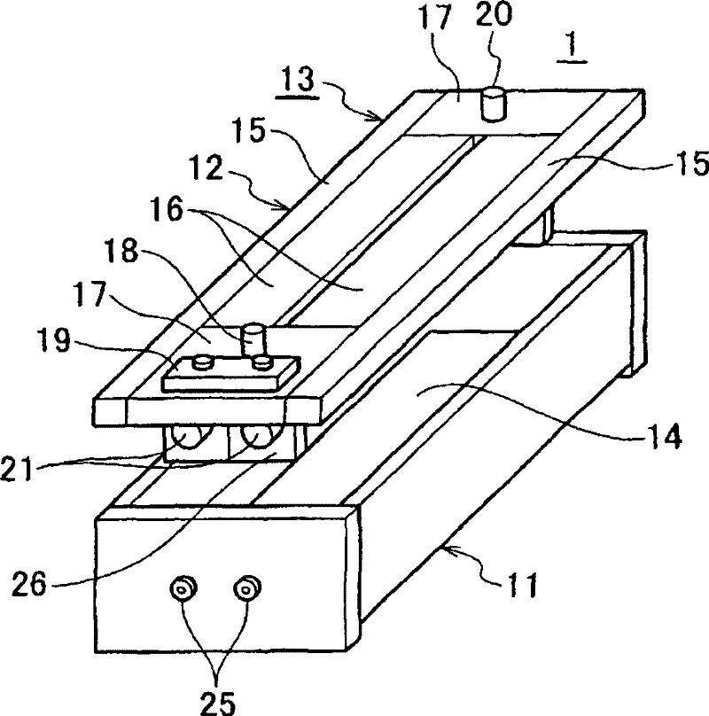
[0034] Such as figure 1 , figure 2 As shown, the ultraviolet irradiation device 1 of the present embodiment includes a lamp housing 13 composed of a frame body 11 and a cover body 12 with an open upper surface. Almost the entire lower surface of the lamp housing 13 serves as an irradiation window, and an ultraviolet transmission window member 14 is attached to the irradiation window portion.

[0035] The cover 12 of the lamp housing 13 is composed of side members 15 on both sides, an external electrode block 16 constituting a cooling material and external electrode constituting member, and a low-voltage terminal block 17 . One low-voltage terminal block 17 is provided with a nitrogen inflow port 18 and a low-voltage terminal block 19 , and the other low-voltage terminal block 17 is provided with a nitrogen outflow port 20 .

[0036] In this embodiment, the lamp housing 13 accommodates two dielectric barrier discharge lamps 21 each equipped with an outer electrode block 16 ....

no. 2 approach

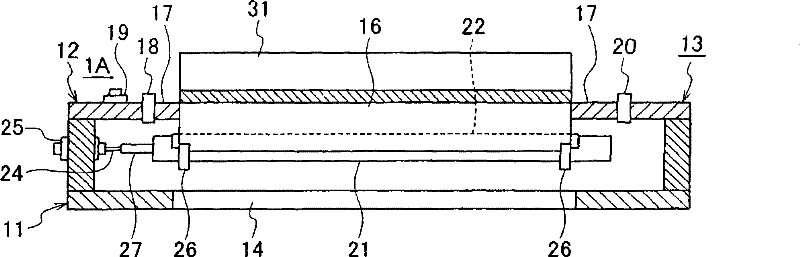
[0042] image 3 The ultraviolet irradiation apparatus 1A which concerns on 2nd Embodiment of this invention is shown. The ultraviolet irradiation device 1A of this embodiment is relative to figure 1 , figure 2The ultraviolet irradiation device 1 of the first embodiment shown in , is characterized in that a heat sink block 31 of a heat sink structure is provided in close contact with the outer surface of the external electrode block 16 forming a part of the cover body 12 of the lamp housing 13 . For example, the heat dissipation block 31 is fixed to the outer surface of the external electrode block 16 with an adhesive (hatched portion in the figure) made of a silicon member for heat dissipation.

[0043] And, in image 3 In the second embodiment shown in , the same reference numerals are used to indicate the figure 1 , figure 2 The constituent elements are the same as those of the first embodiment shown in FIG.

[0044] According to this embodiment, by arranging the hea...

no. 3 approach

[0046] Figure 4 , Figure 5 The ultraviolet irradiation apparatus 1B which concerns on 3rd Embodiment of this invention is shown. The ultraviolet irradiation device 1B of this embodiment is relative to figure 1 , figure 2 The first embodiment shown in FIG. 1 is characterized in that each external electrode block 16A prepared according to the number of lamps constituting the cover body 12 has a heat sink structure. That is, the grooved groove 22 is formed on the lower surface of the external electrode block 16A so as to be in close contact with the upper half peripheral surface of the dielectric barrier discharge lamp 21, and the heat sink 41 is formed on the upper surface of the external electrode block 16A. As in the first and second embodiments, the outer electrode block 16A that is in close contact with the dielectric barrier discharge lamp 21 is made of aluminum or stainless steel, which is a conductive material excellent in thermal conductivity. And, in Figure 4 ,...


PUM


Abstract

The invention provides an ultraviolet irradiation apparatus with structure for reducing desired nitrogen quantity for cooling lamp. The ultraviolet irradiation apparatus comprises: a dielectric medium stop electric discharge lamp (21) for radiation ultraviolet, a sealing lamp housing (13) for accommodating the dielectric medium stop electric discharge lamp, a nitrogen supply section (18) for supplying nitrogen gas into the lamp housing, a low-voltage terminal block (17) composing cover body (12) of the lamp housing, and an outer electrode block (16) projecting outside of the lamp housing fromthe low-voltage terminal block (17), and forming concave groove (22) having accordant shape with upper part of the dielectric medium stop electric discharge lamp on the outer electrode block (16). The invention is characterized in that the outer electrode block (16) is composed of the concave groove and conductive component clinging with the upper part periphery surface of the dielectric medium stop electric discharge lamp, the conductive component is also cooling material at the same time of composing electrode.

Description

technical field [0001] The present invention relates to an ultraviolet irradiation device. Background technique [0002] Generally, when dry-cleaning circuit boards, such as a liquid crystal board|substrate, the ultraviolet irradiation apparatus which used the dielectric barrier discharge lamp (Dielectric Barrier Discharge Lamp) is used. This dielectric barrier discharge lamp is an excimer lamp composed of a quartz glass tube in which an excimer-generating gas is sealed. Therefore, by applying a high-frequency voltage to the excimer lamp, the excimer-generating gas in the quartz glass tube can be brought into an excimer state, and a single-wavelength ultraviolet light with a wavelength of 172 nm can be emitted. By irradiating the ultraviolet rays with a wavelength of 172nm on an object to be irradiated such as a circuit board in the atmospheric atmosphere, the oxygen in the atmosphere is decomposed to generate active oxygen, and the organic compound with the broken bond rea...

Claims


Application Information

Patent Timeline
Patent Type & Authority Patents(China)
IPC IPC(8): H01J65/04H01J61/52F21V15/02
Inventor 八岛诚前田祥平仓谷晶子玉井幸一
Owner HARISON TOSHIBA LIGHTING CORP
Why Eureka
Try Eureka