Interference type integral photo-signal modulator and preparation thereof

An integrated, optical signal technology, applied in light guides, optics, instruments, etc., can solve the problems of polarization state control, electrode packaging difficulties, and inability to achieve stable modulation, and achieve the effect of simple structure and improved performance

Inactive Publication Date: 2009-02-18
HARBIN ENG UNIV
View PDF1 Cites 21 Cited by
  • Summary
  • Abstract
  • Description
  • Claims
  • Application Information

AI Technical Summary

Problems solved by technology

In addition, the modulation electrodes in this experiment are mechanically pressed on the optical fiber, and there is no practical packaging of the electrodes. Therefore, this experiment has difficulties in polarization state control and electrode packaging, and it is impossible to achieve long-term stable modulation.

Method used


Image

  • Interference type integral photo-signal modulator and preparation thereof
  • Interference type integral photo-signal modulator and preparation thereof
  • Interference type integral photo-signal modulator and preparation thereof

Examples


specific Embodiment approach 1

[0058] Specific Embodiment 1: Fabricate an interference-type integrated optical signal modulator by thermal polarization method and ultraviolet laser micromachining.

[0059] Proceed as follows:

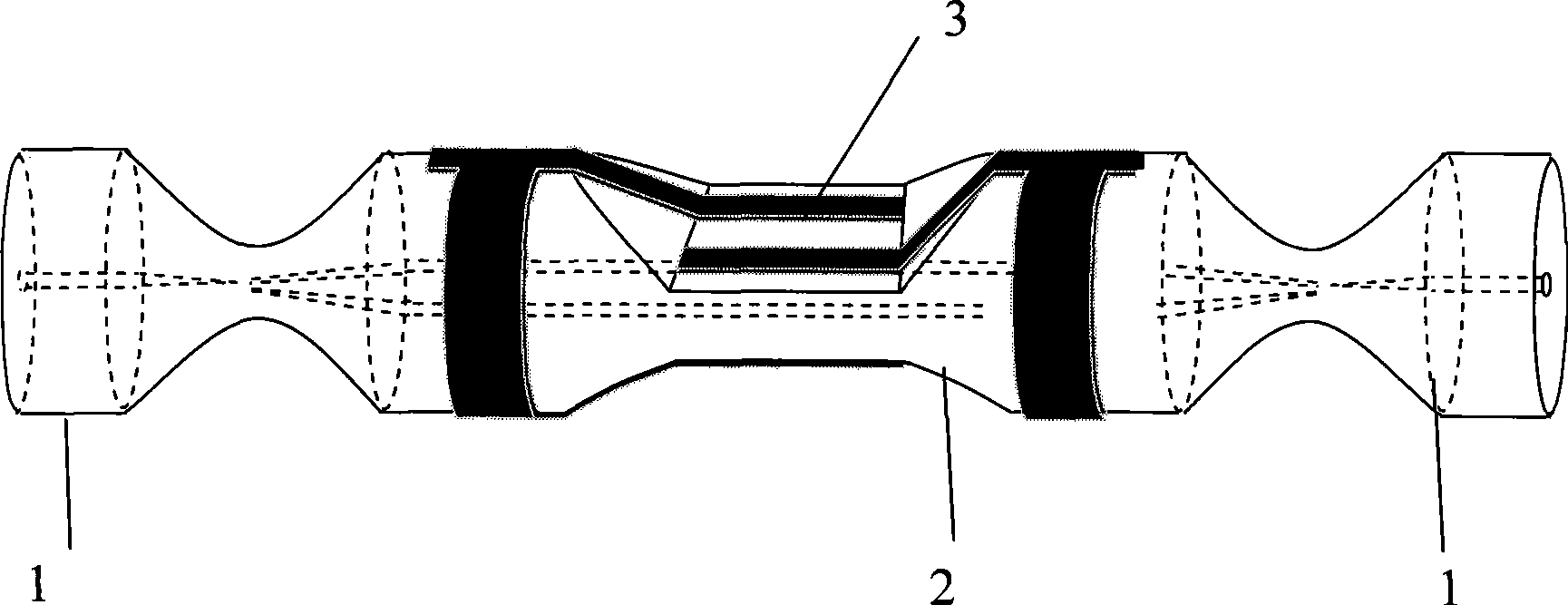
[0060] 1. Take two sections of standard single-mode optical fiber 1 respectively, use optical fiber strippers to strip the coating layer of the optical fiber for about 30mm, clean the optical fiber cladding with a mixture of alcohol and ether, and cut the end face of the optical fiber flat with an optical fiber cutter. Clean the fiber cladding again.

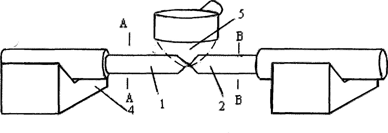
[0061] 2. Take a section of double-core optical fiber 2 with a length of 400mm, and use optical fiber strippers to strip the coating layer of the optical fiber for about 30mm, clean the optical fiber cladding with a mixture of alcohol and ether, and use an optical fiber cutter to clean the two end faces of the optical fiber. Cut flat, and clean the fiber cladding again.

[0062] 3. Solder the two ends of the standard single-mode opti...

specific Embodiment approach 2

[0072] Specific embodiment 2, using the ultraviolet polarization method and ultraviolet laser micromachining to fabricate an interference type integrated optical signal modulator.

[0073] Proceed as follows:

[0074] 1. Take two sections of standard single-mode optical fiber 1 respectively, use optical fiber strippers to strip the coating layer of the optical fiber for about 30mm, clean the optical fiber cladding with a mixture of alcohol and ether, and cut the end face of the optical fiber flat with an optical fiber cutter. Clean the fiber cladding again.

[0075] 2. Take a section of double-core optical fiber 2 with a length of 400mm, and use optical fiber strippers to strip the coating layer of the optical fiber for about 30mm, clean the optical fiber cladding with a mixture of alcohol and ether, and use an optical fiber cutter to clean the two end faces of the optical fiber. Cut flat, and clean the fiber cladding again.

[0076] 3. Solder the two ends of the standard si...


PUM

PropertyMeasurementUnit
diameteraaaaaaaaaa
refractive indexaaaaaaaaaa

Abstract

The invention provides an interferometric integration optical signal modulator and a preparing method thereof, which comprises two sections of standard single-mode fiber and a polarization dual-chip optical fiber which is provided with two pairs of microelectrodes, two sections of the standard single-mode fiber are jointed at both ends of the polarization dual-chip optical fiber which is provided with two pairs of microelectrodes in coupling way by utilizing the fusion coupling method to form the Mach-Zehnder interferometer structure, light which is imported from the single-mode fiber can be evenly distributed in two arms of the Mach-Zehnder interferometer which is composed of the polarization dual-chip optical fiber, two pairs of the microelectrodes can execute the phase modulation for the light in both arms through adopting the differential modulation way, two beams of light interfere mutually in a coupling part and then can be exported by the single-mode fiber, and the phase separation of two beams of light can make the light intensity modulated. The modulator has simple structure, can keep relative stability between the light paths, can effectively avoid influence from environment factors such as vibration, temperature and the like, and can greatly improve the performance of the full optical fiber electro-optical modulator.

Description

(1) Technical field [0001] The invention relates to an interference type integrated optical signal modulator, which belongs to the field of optical fiber active devices. (2) Background technology [0002] Optoelectronic devices are the most important basis for the development of optical communication and optical sensing. At present, various new optoelectronic devices emerge in an endless stream, and the performance of optoelectronic devices is continuously improved. The integration of optical devices is the only way to meet people's demand for optoelectronic devices. Although the concept of "integrated optics" appeared for the first time in the late 1960s, the main idea is to build various optical devices on a common substrate, and then connect them with waveguides to form a system that can perform specific functions. chip. Integrated optical devices have the advantages of small size, stable polarization state, easy photoelectric integration, mass production and precision...

Claims


Application Information

Patent Timeline
Patent Type & Authority Applications(China)
IPC IPC(8): G02F1/225G02B6/255G02B6/00
Inventor 苑立波刘志海杨军
Owner HARBIN ENG UNIV
Why Eureka
Try Eureka