Pressure type oil-contaminated water air-float machine

A pressure-type, oil-polluted technology, which is applied in water/sewage treatment, water/sludge/sewage treatment, liquid separation, etc., can solve the problems of easy fouling and high conductivity of the plate, and reduce the amount of dosing and occupy The effect of small floor area and flexible equipment structure

Inactive Publication Date: 2009-03-18
JIANGDU COUNTY ENVIRONMNT PROTECTION EQUIPS FACTORY
View PDF0 Cites 2 Cited by
  • Summary
  • Abstract
  • Description
  • Claims
  • Application Information

AI Technical Summary

Problems solved by technology

[0006] The invention has the advantages of being able to operate under normal pressure or under pressure, flexible equipment structure (it can be placed upright or lying down), reducing the amount of dosing, low operating cost, small footprint, etc., and also solves the problem of easy fouling of the pole plate , can be widely used in the treatment of oily wastewater from oilfields, petroleum, petrochemicals, and tertiary oil recovery wastewater in the late stage of oilfield mining. It can also be used in the treatment of industrial wastewater with high salinity and high conductivity such as leather and pesticide production wastewater. It is also suitable for Treatment of sewage with high salinity and high conductivity such as leather production sewage and some pesticide production sewage

Method used


Image

  • Pressure type oil-contaminated water air-float machine

Examples


Embodiment Construction

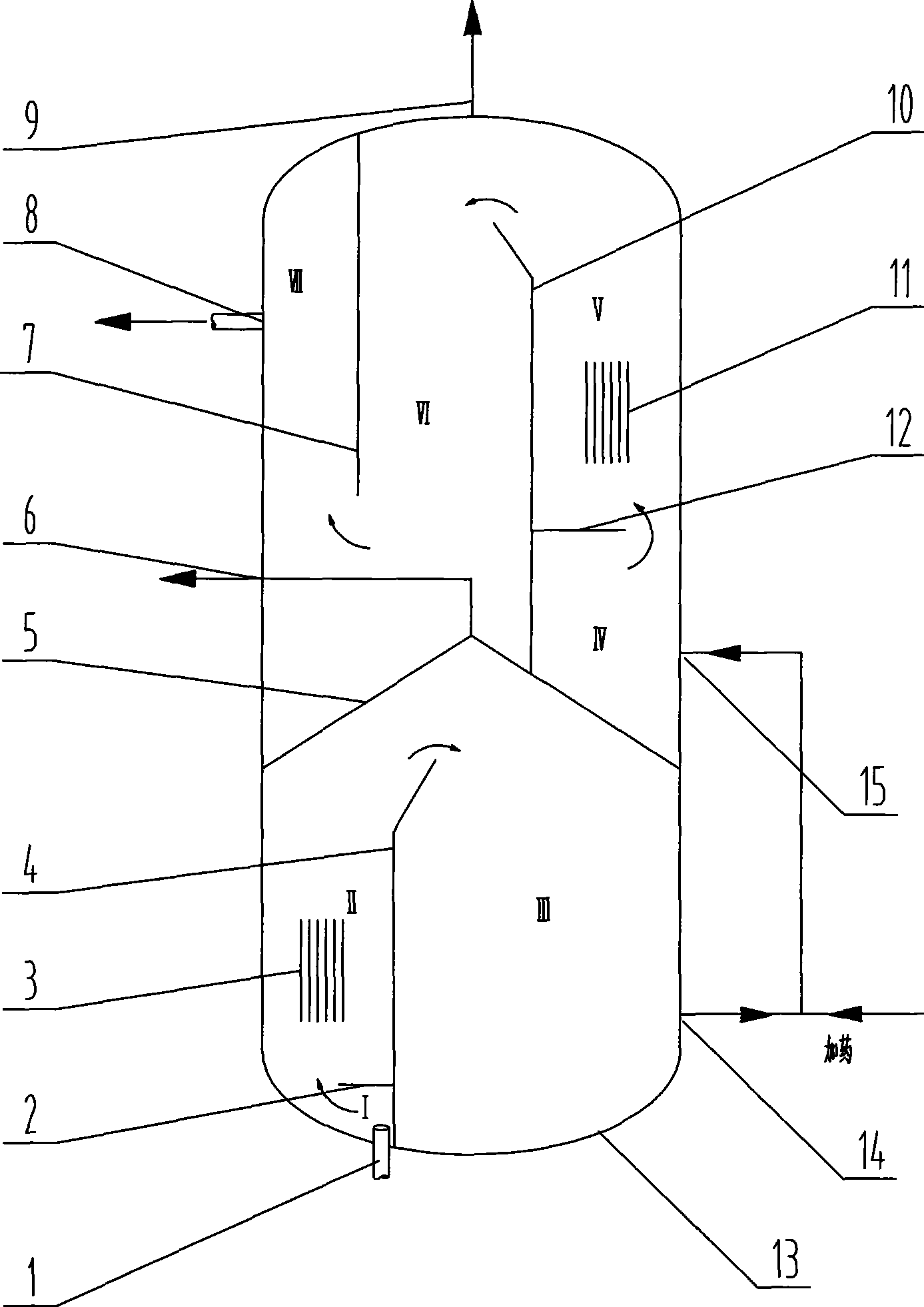
[0009] Such as figure 1 As shown, the water inlet 1 is set at the lower bottom of the casing 13, and the inner cavity of the casing 13 is divided into upper and lower chambers (the lower chamber is a first-level electric floating chamber, and the upper chamber is a second-level electrical floating chamber). The transverse partition 5 of the floating chamber), the transverse partition 5 is a cone whose middle part is higher than the periphery. An oil discharge port A 6 communicating with the outside of the casing 13 is provided at the top of the transverse partition 5 .

[0010] A vertical baffle A 4 is arranged below the transverse partition 5 of the inner cavity of the casing 13 , the lower end of the vertical baffle A 4 is connected to the lower bottom of the casing 13 , and a gap is set between the upper end and the transverse partition 5 . The electrode A3 is arranged on one side of the inner cavity of the casing 13 facing the baffle A4, and the water inlet 1 is arranged ...


PUM


Abstract

The invention discloses a pressure type oily water floatation machine, and more particularly relates to the technical field of an oily water treating floating device. A water inlet is installed at the lower bottom of a shell, a horizontal clapboard is installed inside the shell, and an oil and air outlet A is installed at the top end of the horizontal clapboard; a vertical baffle A is installed under the horizontal clapboard in the inner cavity of the shell, an electrode A is arranged at one side of the vertical baffle A, a first-grade liquid outlet is arranged at the other side, and a horizontal baffle A is connected with the vertical baffle A; a vertical baffle B is arranged above the horizontal clapboard, a horizontal baffle B is connected with the vertical baffle B, a second-grade liquid inlet is arranged under the horizontal baffle B, and an electrode B is arranged above the horizontal baffle B; a vertical baffle C is arranged at the other side of the vertical baffle B, a water outlet is arranged at one side of the vertical baffle C, and an oil and air outlet B is arranged at the top part of the shell at the other side. The pressure type oily water floatation machine has the advantages of being capable of operating under normal pressure as well as increased pressure, being flexible in equipment structure (placing in either a standing mode or a lying mode), reducing drug amount, being low in operation cost and small in floor space.

Description

Technical field: [0001] The invention relates to the technical field of an air flotation device for oily sewage treatment. technical background: [0002] Many oil fields have entered the middle and late stages of development, and the water content of oil and gas well production fluids has increased year by year. If these production fluids containing crude oil and suspended solids are not treated effectively, whether they are reinjected into the ground or discharged, they will cause great harm to the environment. . Therefore, oilfield sewage treatment has become an important work in oilfield production. [0003] Constantly seeking more energy-saving and efficient treatment processes and devices is an effective way to improve economic benefits in the oilfield industry. At present, there are many types of oilfield sewage treatment processes and equipment, and the main typical treatment methods are divided into: physical method, chemical dosing method, coarse granulation metho...

Claims


Application Information

Patent Timeline
Patent Type & Authority Applications(China)
IPC IPC(8): B01D17/035C02F1/00
Inventor 虞荣松艾华马宏庆任惠子汤卫刚
Owner JIANGDU COUNTY ENVIRONMNT PROTECTION EQUIPS FACTORY
Why Eureka
Try Eureka