
Capacitance single mass three-shaft acceleration transducer and preparation method

A shaft acceleration and single-mass technology, applied in piezoelectric/electrostrictive/magnetostrictive devices, televisions, generators/motors, etc., can solve problems such as high packaging complexity, increased process difficulty, and large chip area , to achieve the effect of avoiding quadrature mismatch error, good off-axis sensitivity characteristics, and reducing sensor area

Active Publication Date: 2009-03-18
MEMSENSING MICROSYST SUZHOU CHINA
View PDF0 Cites 40 Cited by
  • Summary
  • Abstract
  • Description
  • Claims
  • Application Information

AI Technical Summary

Problems solved by technology

[0005] Although a variety of micro-machined acceleration sensors have been developed, most of them can only detect the acceleration of one or two axes, and cannot detect the acceleration of three axes at the same time
The solution usually adopted today is to assemble several uniaxial acceleration sensors orthogonally, but the packaging complexity is high, not only the efficiency is low, but also it is easy to introduce a large orthogonal mismatch error; another method that can be adopted is in the Make three uniaxial accelerometers on the same chip to measure acceleration in different directions to solve quadrature mismatch error
But this will increase the difficulty of the process and occupy a large chip area

Method used


Image

  • Capacitance single mass three-shaft acceleration transducer and preparation method
  • Capacitance single mass three-shaft acceleration transducer and preparation method
  • Capacitance single mass three-shaft acceleration transducer and preparation method

Examples


Embodiment 1

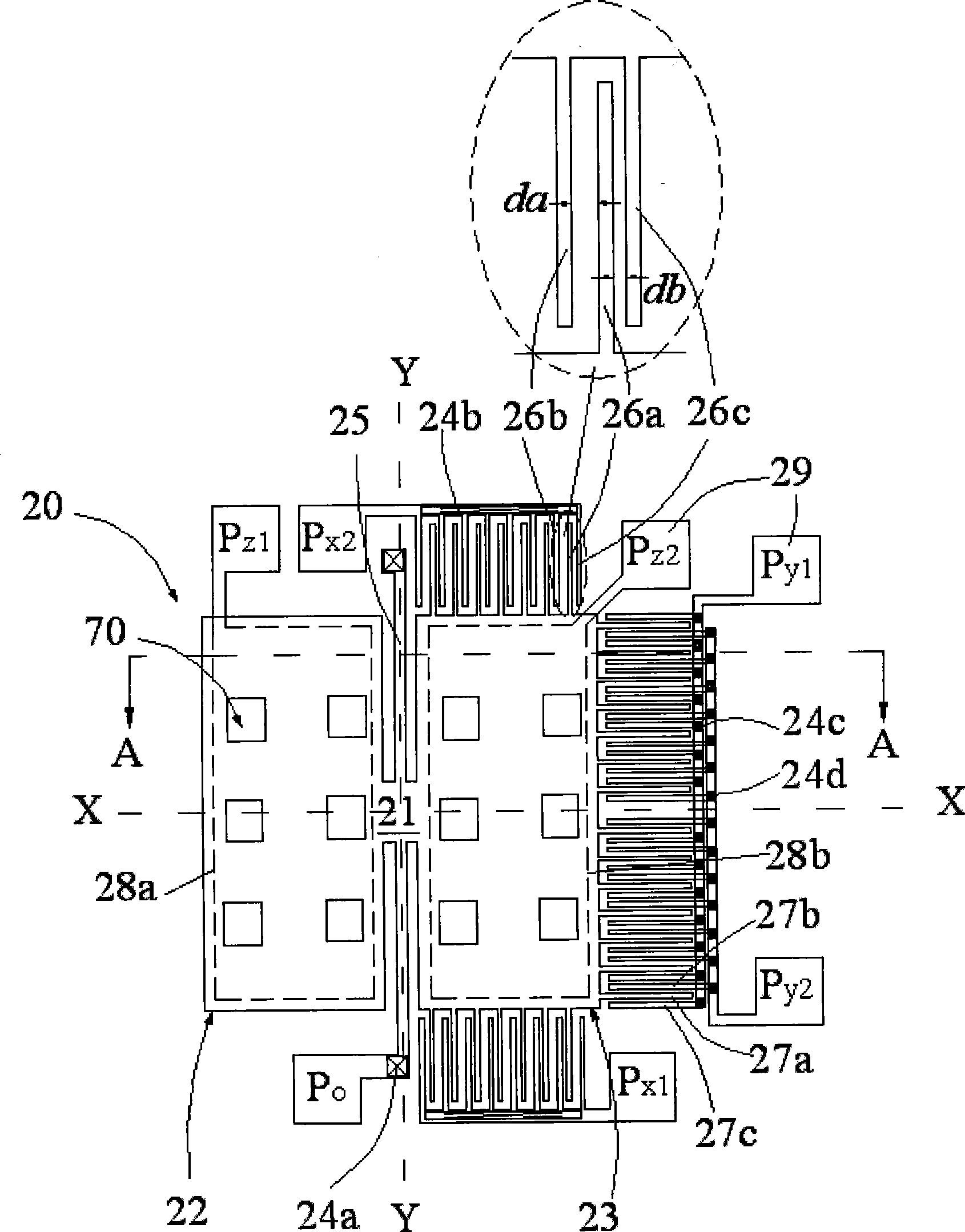
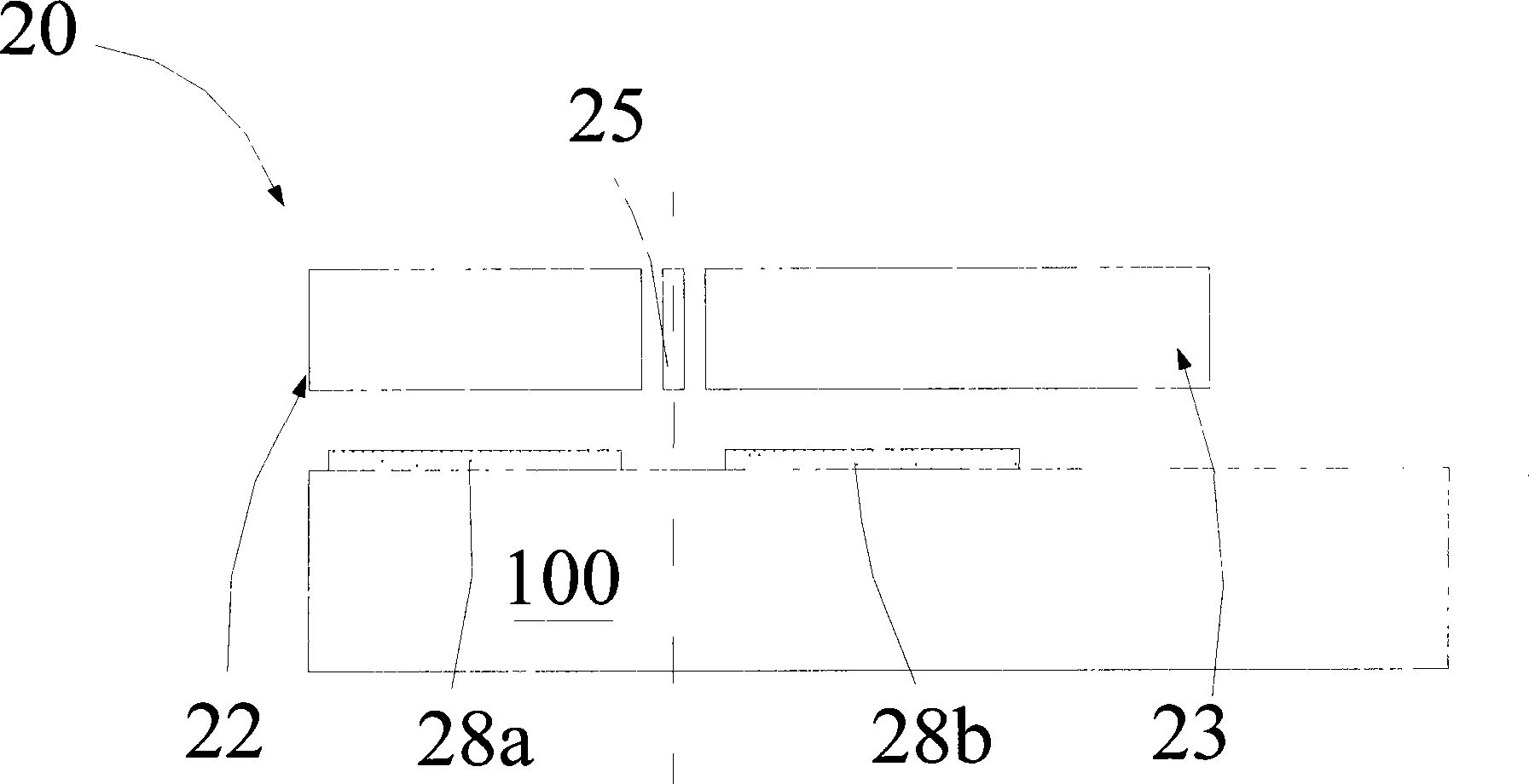
[0025] see Figure 1A and 1B , the capacitive single-mass triaxial acceleration sensor 20 of the present invention at least includes: a substrate 100, a mass area 21, a comb-tooth structure area and a signal output area.

[0026] The substrate 100 includes a substrate and a dielectric insulating layer formed on the substrate. The dielectric insulating layer may be a single-layer structure or a multi-layer structure, such as a composite composed of silicon oxide and silicon nitride. Floor.

[0027]The mass region 21 includes a first conductive layer formed on the dielectric insulating layer, a cantilever beam 25 located on the first conductive layer and connected to the dielectric insulating layer at a fulcrum, and connected to the cantilever beam One side of 25 and the first conductive layer form a first movable block 22 as a first bifurcated capacitor, connected to the other side of the cantilever beam 25 and at the same level as the first movable block 22 and at the same t...

Embodiment 2

[0034] See figure 2 , which is the top view of the second embodiment of the capacitive single-mass three-axis acceleration sensor of the present invention. like figure 2 As shown, the capacitive single-mass triaxial acceleration sensor 30 includes a mass region 31 and a comb-tooth structure region formed by three sets of interdigital capacitors and disposed outside the mass-block region 51 , wherein the mass The area 31 is composed of a first movable block 32, a second movable block 33 and a cantilever beam 35 for supporting, and both ends of the cantilever beam 35 are fixed on the substrate through fulcrums 34a. The only difference from the first embodiment is that the second group of comb structures for measuring the X-axis acceleration is connected to the first movable block 32 , and the second movable block 33 has a larger mass than the second movable block 23 in the first embodiment. Since the combined region formed by the mass region 31 and the comb-tooth structure r...

Embodiment 3

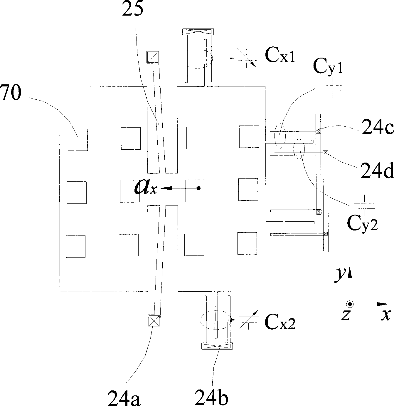
[0037] See image 3 , which is the top view of the third embodiment of the capacitive single-mass three-axis acceleration sensor of the present invention. The capacitive single-mass triaxial acceleration sensor 40 includes a mass region 41 and three sets of interdigital capacitances formed by comb-tooth structure regions disposed outside the mass region 51 , wherein the mass region 41 is formed by a first movable block. 42. The second movable block 43 and the supporting cantilever beam 45 are composed. The difference from the first embodiment is that the first movable block 42 and the second movable block 43 are formed by the cantilever beam 45 at the outer ring of the two. For support, the cantilever beam 45 is fixed to the substrate through a fulcrum 44a located in the middle portion of the proof-mass region 41 . Because the combined region formed by the mass region 41 and the comb-tooth structure region has two asymmetrical left and right parts. The design that the fulcru...


PUM


Abstract

The invention relates to a capacitive triaxial acceleration transducer with a single mass block and a preparation method thereof. A mass block region and a comb structure region are formed on a substrate, wherein, the mass block region comprises a first conducting layer, a socle beam which is positioned on the first conducting layer and is in fulcrum connection with the substrate, and a first block and a second movable block which are respectively connected with the two sides of the socle beam; the movable blocks and the first conducting layer form a differential capacitor used for measuring the accelerated speed in the first direction; the comb structure region is formed on the same layer with the mass block region, which comprises a first group of comb structure which is formed on the outer side of the second movable block and is used for measuring the accelerated speed in the second direction, and a second group of comb structure which is symmetrically formed on the opposite two natural sides of any movable block and is used for measuring the accelerated speed in the third direction; and furtherer more, the gravity of a combined region formed by the mass block region and the comb structure region deviates from the socle beam; therefore, the triaxial acceleration transducer formed by adopting the single mass block can realize the function of measuring the vector acceleration.

Description

technical field [0001] The invention relates to a capacitive single-mass-block three-axis acceleration sensor and a preparation method. Background technique [0002] Micro-Electro-Mechanical Systems (MEMS) technology is a high-tech technology that has developed rapidly in recent years. It mainly adopts advanced semiconductor fabrication technology to realize the fabrication of MEMS devices in batches. Compared with corresponding devices made by traditional technology, MEMS devices have obvious advantages in terms of volume, power consumption, weight and price. [0003] As a kind of inertial device, acceleration sensor is widely used in aerospace, automobile, machinery industry, and consumer electronics. Among MEMS devices, the research on micro-silicon accelerometer was earlier, beginning in the early 1980s. It has the advantages of small size, light weight, convenience and dexterity, mass production, and cost reduction. More importantly, due to its size Shrinkage and cost...

Claims


Application Information

Patent Timeline
IPC IPC(8): B81B7/02B81C1/00
Inventor 李刚胡维
Owner MEMSENSING MICROSYST SUZHOU CHINA
Learn More