Eureka AIR delivers breakthrough ideas for toughest innovation challenges, trusted by R&D personnel around the world.

Miniature fluid cooling system and miniature fluid driving device

A cooling system, micro-liquid technology, applied in the components of pumping devices for elastic fluids, liquid fuel engines, liquid variable displacement machinery, etc., can solve the cooling needs that cannot be met, difficult electronic component cooling, mechanical pumps Large space and other issues, to achieve good quiet effect, best cooling performance, simple process effect

Inactive Publication Date: 2009-03-18
FU ZHUN PRECISION IND SHENZHEN +1
View PDF0 Cites 37 Cited by
  • Summary
  • Abstract
  • Description
  • Claims
  • Application Information

AI Technical Summary

Problems solved by technology

[0004] Due to the large space occupied by the mechanical pump in the traditional liquid cooling system, it is difficult to cool electronic components in electronic devices with small internal spaces such as notebook computers
In order to miniaturize the liquid cooling system, the industry has carried out research on various micropumps, including research on piezoelectric pumps using vibrating piezoelectric diaphragms. However, piezoelectric pumps currently used in micro-sized liquid cooling systems The efficiency of the cooling liquid that the pump can transfer is not high, and it cannot meet the demand for cooling electronic components such as CPUs that generate increasing heat
In addition, currently used piezoelectric pumps usually need to be equipped with a movable check valve that uses pressure difference to open and close. This will not only cause vibration and noise due to the movable opening and closing characteristics of the check valve, but also relatively reduce Drive Coolant Reliability

Method used


Image

  • Miniature fluid cooling system and miniature fluid driving device
  • Miniature fluid cooling system and miniature fluid driving device
  • Miniature fluid cooling system and miniature fluid driving device

Examples


Embodiment Construction

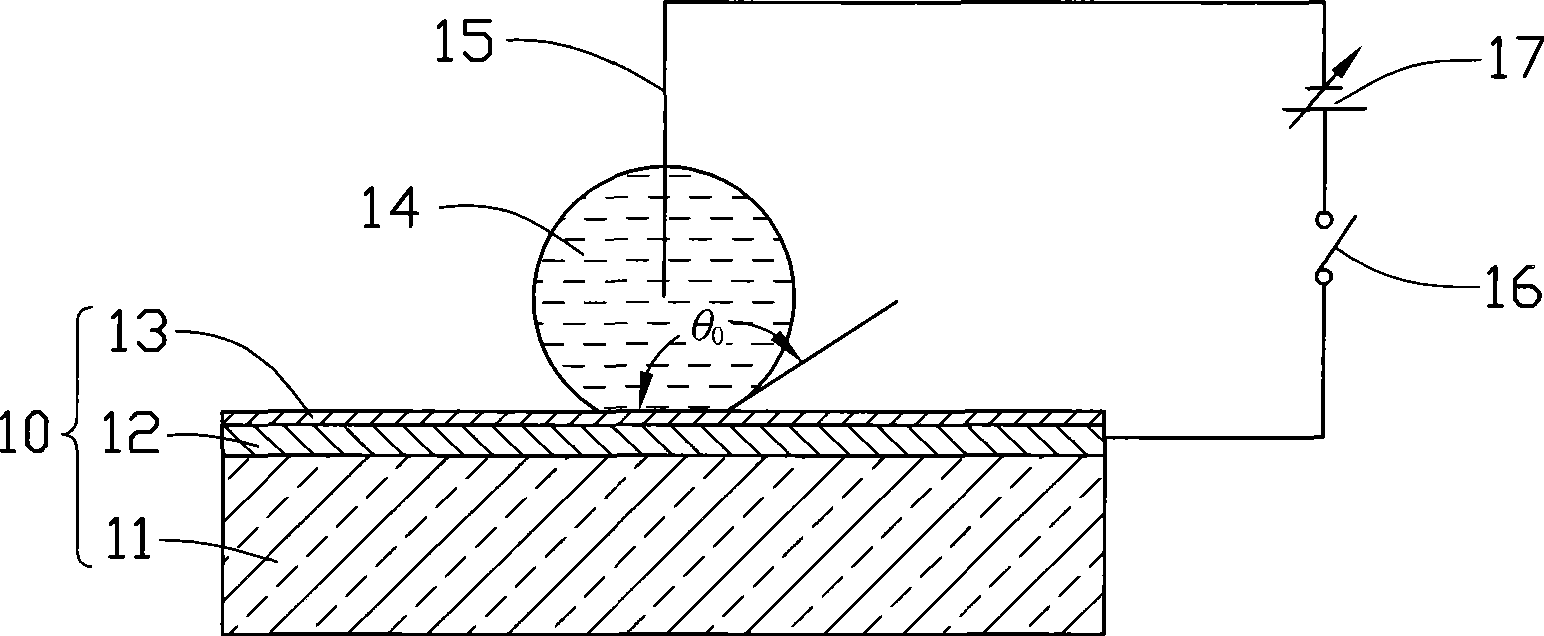
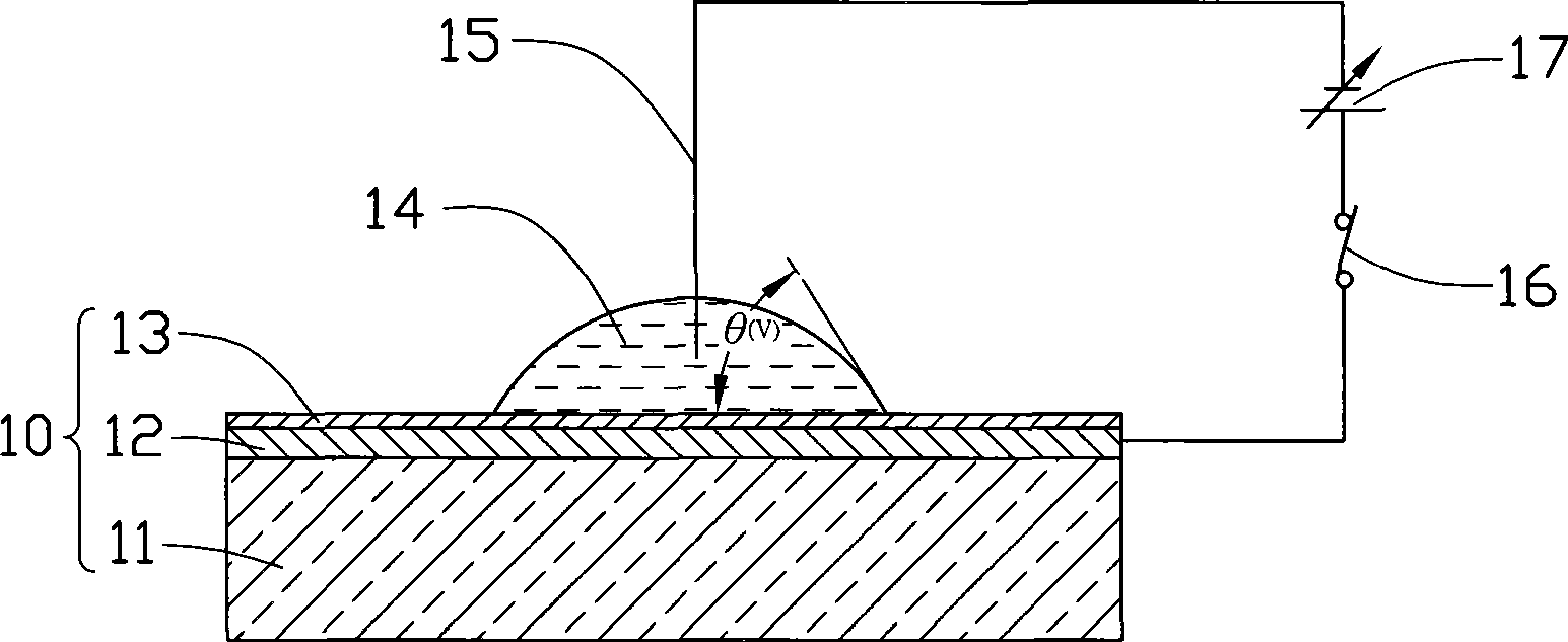
[0024] The invention aims to apply the microfluidic control technology based on the electric wetting effect on the dielectric material to the micro liquid cooling system, and cooperate with a piezoelectric pump to realize the massive transmission of the cooling liquid.

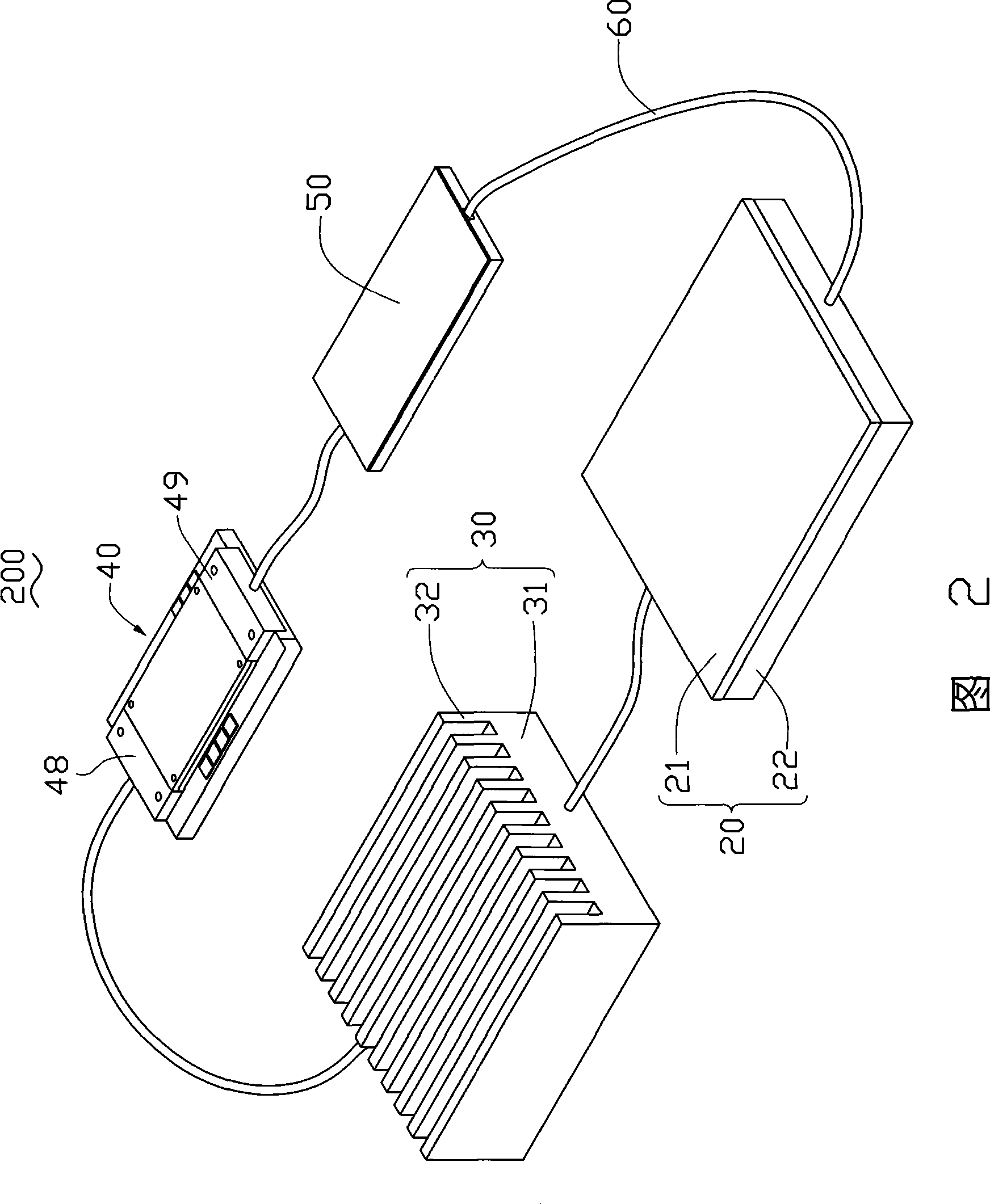
[0025] FIG. 2 is a three-dimensional assembly view of a preferred embodiment of the micro liquid cooling system 200 of the present invention. The micro liquid cooling system 200 includes a heat absorber 20 , a heat sink 30 , a droplet generator 40 , a piezoelectric pump 50 and a plurality of transmission tubes 60 . The heat absorber 20 , heat sink 30 , droplet generator 40 and piezoelectric pump 50 are connected in series through the transmission tubes 60 to form a loop, which is filled with cooling liquid (not shown). The heat absorbing body 20 is thermally connected with a heating electronic component and absorbs the heat generated by it, and the heat sink 30 is used for cooling the cooling liquid flowing th...


PUM


Abstract

The invention provides a micro liquid cooling system, comprising a heat absorber, a heat radiator and a plurality of transferring tubes, a micro liquid drop generator and a piezoelectric pump furthermore. Transferring tubes connects the heat absorber, the heat radiator, the micro liquid drop generator and the piezoelectric pump into one loop having coolant fluid filled therein. The coolant fluid circulates in the loop under commonly driving of the micro liquid drop generator and the piezoelectric pump. The micro cooling system can be used in electronic devices with relatively small internal space and has great cooling performance when cooling electronic elements.

Description

technical field [0001] The invention relates to a micro liquid cooling system, in particular to a micro liquid cooling system for cooling heating electronic components and a micro fluid driving device thereof. Background technique [0002] With the rapid development of the computer industry, the pursuit of high speed CPU, high functionality and miniaturization have caused more and more serious heat dissipation problems, which are more prominent in electronic devices with small internal spaces such as notebook computers. If the heat generated by electronic components such as the CPU in the notebook computer cannot be dissipated in a timely and effective manner, the performance of the electronic components will be greatly affected, and the service life of the electronic components will also be reduced. Therefore, the industry usually uses a cooling device to cool the electronic components. Components dissipate heat. [0003] Among many cooling technologies, liquid cooling is ...

Claims


Application Information

Patent Timeline
Patent Type & Authority Applications(China)
IPC IPC(8): H05K7/20H01L23/473
CPCH01L2924/0002F04B43/046H05K7/20272F04B53/1077G06F1/20F04B19/006H01L2924/00
Inventor 陈彦志陈冠宇
Owner FU ZHUN PRECISION IND SHENZHEN
Why Eureka
Eureka Blog
Learn More