
Plasma torch for making synthetic silica

A technology for synthesizing silicon dioxide and plasma, which is applied in the direction of plasma, manufacturing tools, glass manufacturing equipment, etc., can solve the problems of time-consuming and expensive, and achieve the effect of increasing deposition rate, low bubble count, compact but complete protection

Inactive Publication Date: 2009-03-18
SILICA TECH LLC
View PDF6 Cites 4 Cited by
  • Summary
  • Abstract
  • Description
  • Claims
  • Application Information

AI Technical Summary

Problems solved by technology

Furthermore, the process including ash deposition requiring subsequent drying and sintering is costly and time consuming, thus there is a need for a faster and less costly method of ash deposition and consolidation

Method used


Image

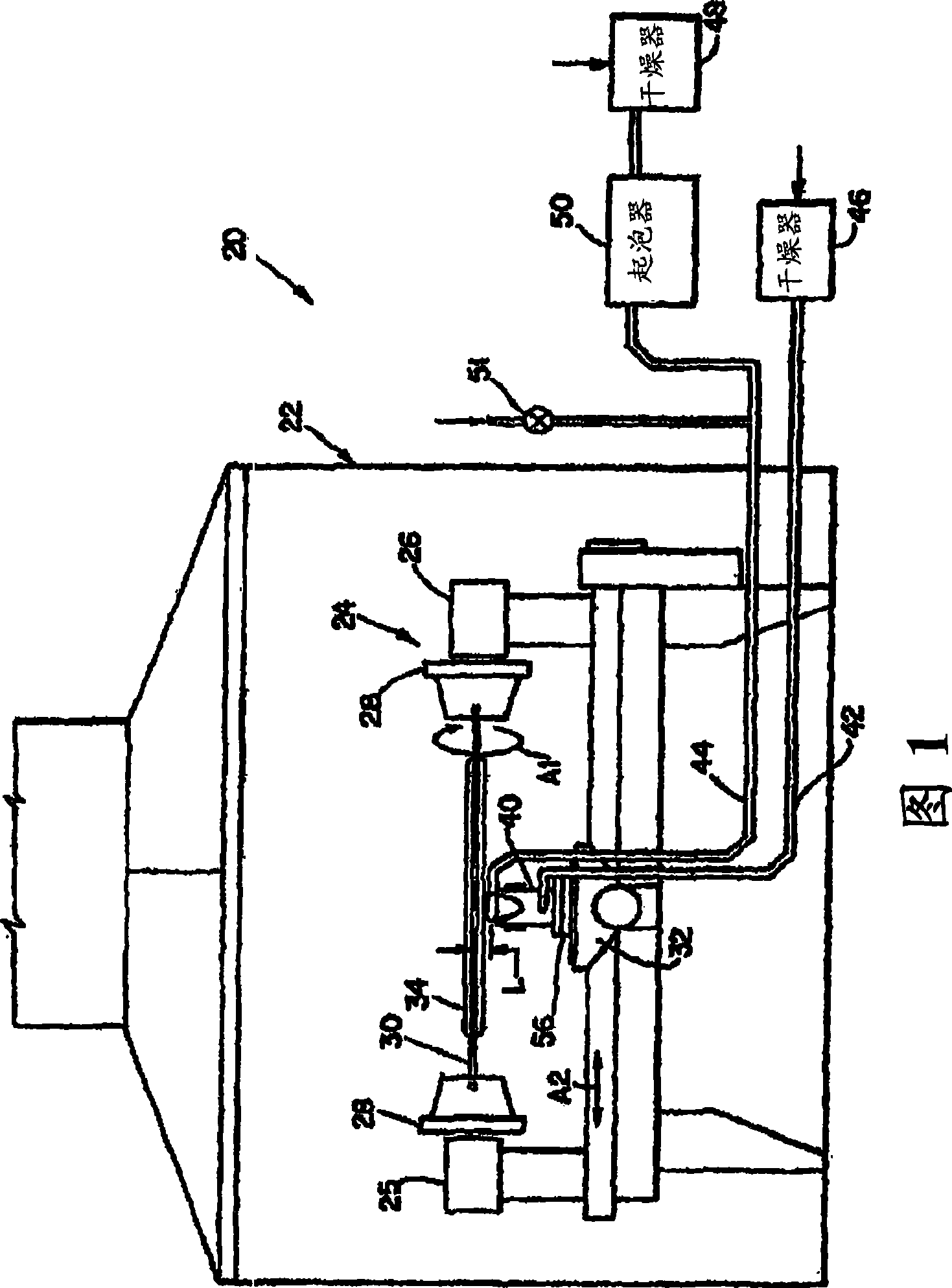
  • Plasma torch for making synthetic silica
  • Plasma torch for making synthetic silica
  • Plasma torch for making synthetic silica

Examples


Embodiment 120

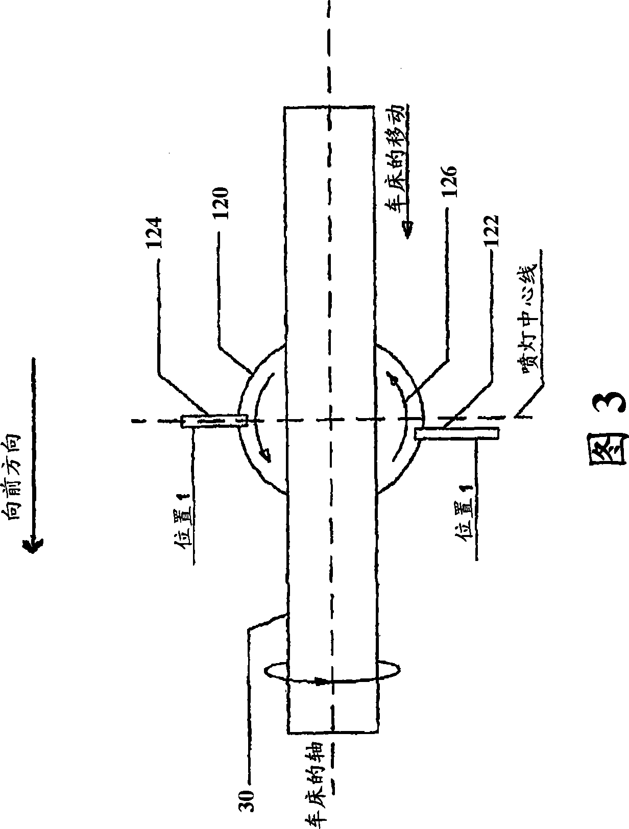
[0047] FIG. 3 illustrates another embodiment 120 of an inductive plasma torch of the present invention having one or more off-center chemical nozzles, a front chemical nozzle 122 and a rear chemical nozzle 124 . Typically, prior art plasma torches include chemical injection ports positioned directly opposite each other. In this embodiment, the rear chemical nozzle 124 is aligned with the centerline of the induction plasma torch 120, while the front chemical nozzle 122 moves forward in the same direction as the rotating object 30, approximately 8 mm in front of the rear chemical torch 124 . With this arrangement shown in Figure 3 and operation in the "forward direction", an increase in deposition rate and better control of the object diameter is achieved. This provides a more uniform diameter of the rotating object 30 .

[0048]Preferably, an offset of 8 mm between the two nozzles provides improved deposition results. In addition, this offset distance may depend on a number ...


PUM

PropertyMeasurementUnit
diameteraaaaaaaaaa
lengthaaaaaaaaaa
diameteraaaaaaaaaa

Abstract

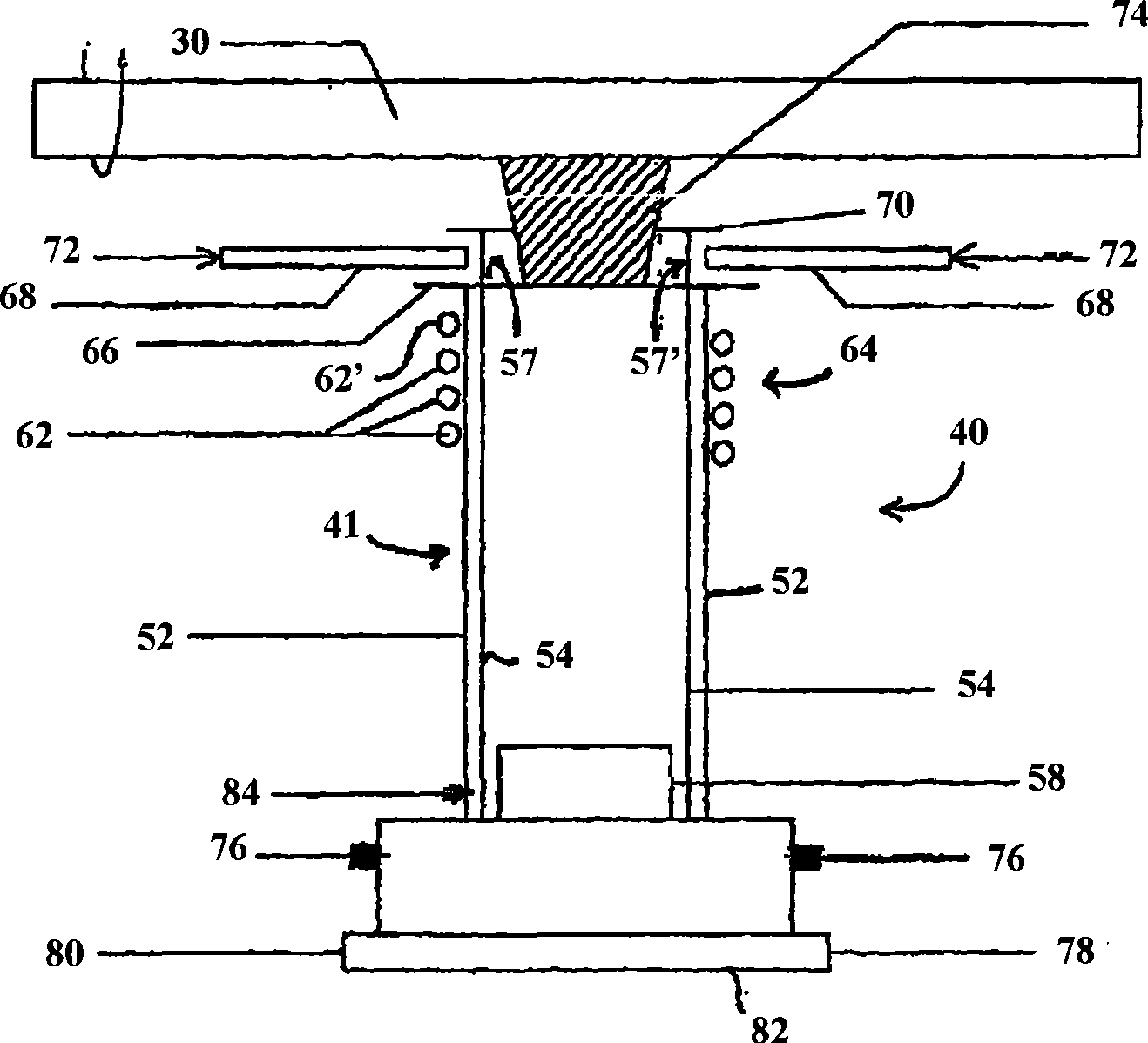
The improved plasma torch (40) for making synthetic silica includes use of nitrogen screen gas from outer quartz tubing (53) to provide active environment isolation. In addition, the present induction plasma torch (40) includes a ring disk (60, 70) for more compact but complete environmental protection (360 degree coverage). It also includes offsetting and switching the position of the chemical injection nozzles (68) for allowing improved deposition in both directions, when operated in a horizontal mode. Further, the present induction plasma torch (40) maintains laminar flow for the injected chemicals and the middle quartz tube (154) is provided with a concave section (157) for increasing the average enthalpy of plasma jet, thus improving the efficiency of the plasma torch. In addition, it may utilize more plasma gas inlets (76). It also includes chemical injection nozzles (68) having a downward angular inclination.

Description

[0001] Cross References to Related Applications [0002] This application claims the benefit of US Provisional Application No. 60 / 754,281 filed December 29,2005. technical field [0003] The present invention relates to blanks for making pure synthetic silica tubes, doped synthetic silica tubes, rods for fiber optic applications and for ultraviolet emitting optical elements. More specifically, it involves the process of depositing silica with low hydroxyl content by a plasma process to make such tubes and optics. Background technique [0004] The prior art teaches various methods for making silica glass starter tubes and for making optical fiber preforms. The starter tube can be made by heating silica and pressing it through the apertures. Initiator tubes and fiber preforms can be fabricated by depositing doped or undoped silica on the object using one of several techniques such as modified chemical vapor deposition (MCVD), vapor axial deposition (VAD), external vapor de...

Claims


Application Information

Patent Timeline
Patent Type & Authority Applications(China)
IPC IPC(8): C03B37/014H05H1/34
CPCC03B2207/81C03B37/01426H05H1/30H05H1/42Y02P40/57
Inventor M·I·古斯科夫M·A·阿斯拉米武韬
Owner SILICA TECH LLC
Learn More