Catalyst multistage regeneration method and device

A technology for regeneration device and catalyst, which is used in catalyst regeneration/reactivation, chemical instruments and methods, physical/chemical process catalysts, etc. effect of time, increased chemical kinetic speed, decreased altitude

Inactive Publication Date: 2009-03-25
QINGDAO JINGRUN PETROCHEM ENG
View PDF8 Cites 22 Cited by
  • Summary
  • Abstract
  • Description
  • Claims
  • Application Information

AI Technical Summary

Problems solved by technology

In this method, because the turbulent bed regenerator adopts a multi-stage countercurrent regeneration method, the average chemical kinetic velocity is relatively high, which improves the regeneration effect of the catalyst. However, because the tubular regeneration is used first, the initial reaction temperature of the spent agent is low, which is difficult to meet the requirements.

Method used


Image

  • Catalyst multistage regeneration method and device
  • Catalyst multistage regeneration method and device
  • Catalyst multistage regeneration method and device

Examples


Embodiment 1

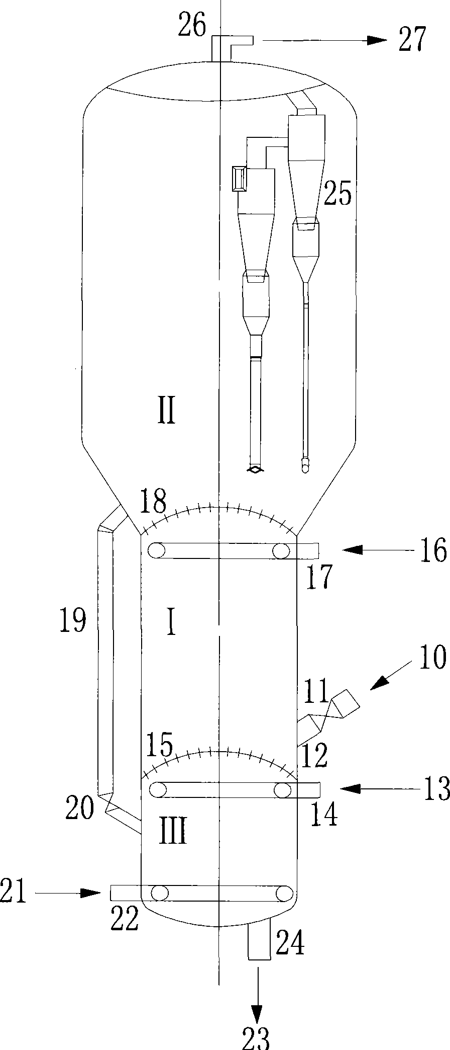
[0040] Example 1: A certain 100×10 4 The t / a catalytic cracking unit is regenerated with compressed air at 200°C. Such as Figure 4 and figure 1 As shown, the carbon content of the regenerated agent 10 is 1.3%, the temperature is 490° C., the carbon content of the outgoing regenerated agent 23 is 0.05%, and the oxygen content in the flue gas 27 at the outlet of the regenerator is about 1%. The distribution plate 15, 18 through-hole flow rate is 15-20m / s, and the amount of catalyst returned through the return pipe 19 is 2.5 times of the circulation volume of the spent agent, and 1.5 times of it enters the first-stage regenerator from the distribution plate 15 to increase the first-stage regeneration temperature. The catalyst in the second stage regenerator enters the third stage after being cooled by the external heat collector 50, and 51 is a slide valve.

[0041] The regeneration temperature, air intake volume, superficial gas flow velocity, char ratio and device height da...

Embodiment 2

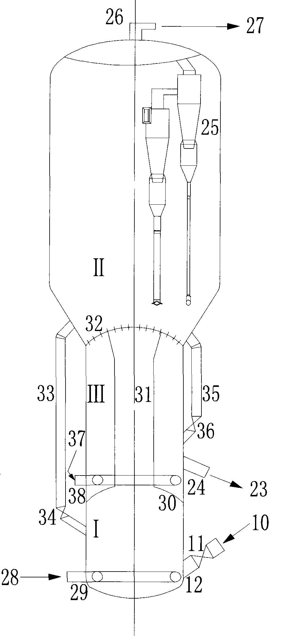
[0048] Embodiment 2: device structure such as figure 2 As shown, the gas superficial flow velocity of each section is 1.2m / s for the first section, 0.8m / s for the second section, and 0.8m / s for the third section; 8m high. The amount of catalyst returned through the return pipe 33 is 1.2 times of the amount to be generated, and the amount of catalyst returned through the catalyst return pipe 35 is 1.5 times of the amount to be generated. Other processing parameters are as embodiment 1.

Embodiment 3

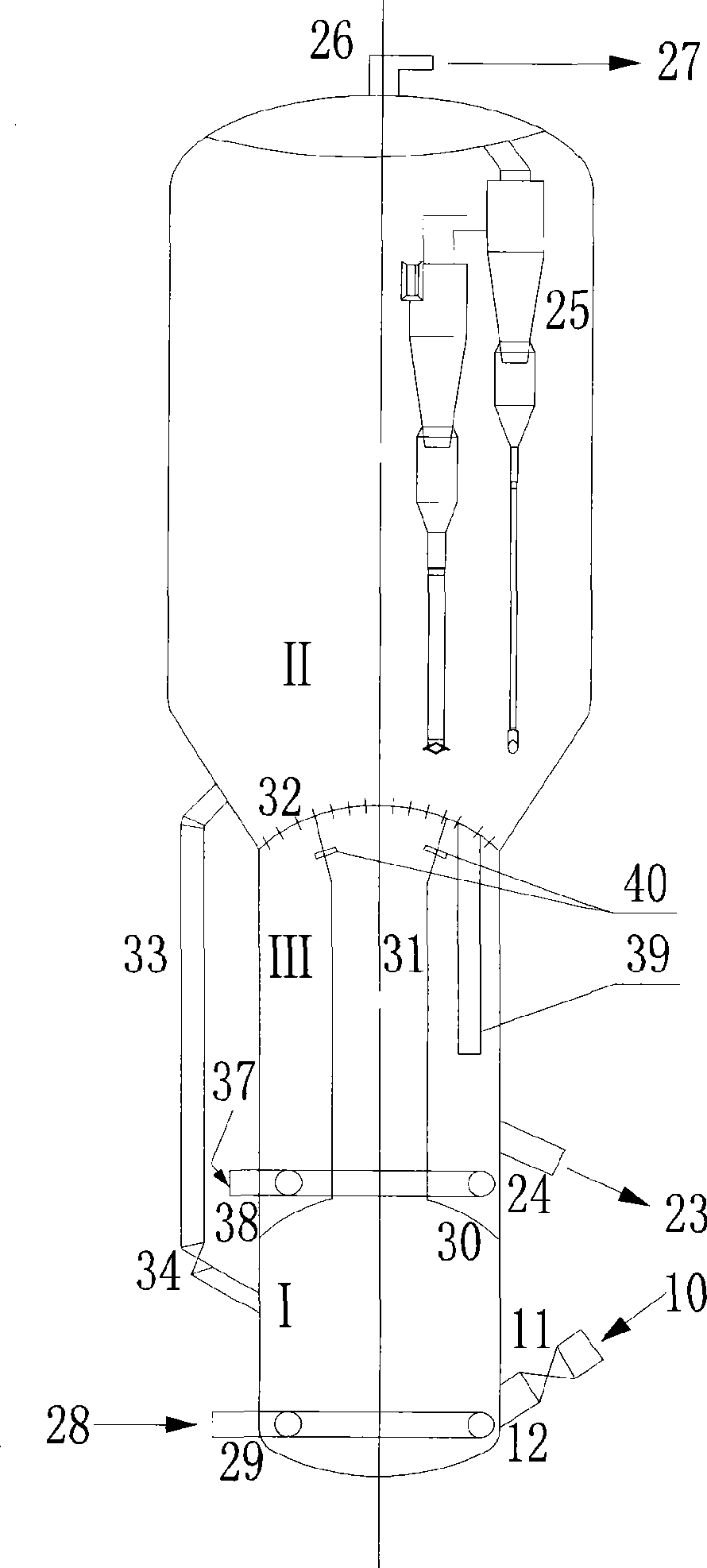
[0049] Embodiment 3: device structure such as image 3 As shown, the catalyst entering the third section through the catalyst return pipe 39 is 1.0-2.0 times of the amount to be produced. Others are the same as embodiment 2.


PUM


Abstract

The invention introduces a catalyst multi-section regeneration method and an apparatus, firstly, a spent catalyst enters a first section regenerator, and is in contact reaction with oxygen-containing gases in the first section regenerator, a second section regenerator and a third section regenerator sequentially, oxygen-containing regeneration flue gas of the first section enters the second section for continuous utilization, and the fresh compressed air is input to the third section for regeneration reaction, so as to complete the whole regenerative process. The fresh compressed air can also be supplemented to the first section regeneration reaction or the second section regeneration reaction, and the catalyst can also reflux to other sections for regeneration. The regeneration apparatus is composed of a first section turbulent bed regenerator, a second section turbulent bed regenerator and a third section turbulent bed regenerator in series connection, a distribution plate or a baffle and a catalyst standpipe are arranged, and all the regenerators are in coaxial arrangement. The invention adopts the multi-section counter-current regeneration, increases the average chemical kinetics speed, strengthens the regenerative process, saves the oxygen-containing gas usage, and reduces the production expense; and realizes the feeding of the spent catalyst from the bottom part or the middle part of each regenerator, lowers the height of the corresponding catalytic conversion device, shortens the oil-gas pipe-line, and reduces the construction investment.

Description

technical field [0001] The invention relates to a petroleum hydrocarbon catalytic conversion technology, in particular to a catalyst multi-stage regeneration method and device. Background technique [0002] The regeneration of coked catalyst is an indispensable process in the fluidized catalytic conversion process of hydrocarbon feedstock, and the investment of the regenerator occupies a large proportion in the investment of the entire catalytic conversion unit, and its energy consumption also accounts for 80% of the energy consumption of the catalytic conversion unit. More than %, and the energy consumption mainly comes from the electric energy consumed by compressing the regeneration gas, improving the utilization rate of the medium and improving the regeneration effect, which is of great significance for reducing the operating cost of the device and reducing the construction investment. Therefore, catalyst regeneration technology and its devices have always been a hot iss...

Claims


Application Information

Patent Timeline
Patent Type & Authority Applications(China)
IPC IPC(8): B01J38/20
Inventor 石宝珍
Owner QINGDAO JINGRUN PETROCHEM ENG
Why Eureka
Try Eureka