Entirety quick manufacture method of hot isostatic pressing metal wrapps

A metal sheath and manufacturing method technology, applied in the field of parts forming and manufacturing, can solve problems such as difficult operation and cumbersome process, and achieve the effects of avoiding pollution, high utilization rate, and shortening the manufacturing cycle

Inactive Publication Date: 2009-03-25
HUAZHONG UNIV OF SCI & TECH
View PDF0 Cites 55 Cited by
  • Summary
  • Abstract
  • Description
  • Claims
  • Application Information

AI Technical Summary

Problems solved by technology

However, this kind of process only uses the rapid prototyping method to manufacture complex local structures in the sheath, and then splicing each local structure into a whole, and after hot isostatic pressing, the sheath needs to be removed by acid etching and other methods. The process is cumbersome and the operation is difficult. larger

Method used


Image

  • Entirety quick manufacture method of hot isostatic pressing metal wrapps
  • Entirety quick manufacture method of hot isostatic pressing metal wrapps
  • Entirety quick manufacture method of hot isostatic pressing metal wrapps

Examples


example 1

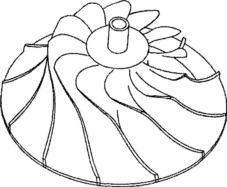
[0022] (1) Firstly, according to the possible deformation of SLM parts after hot isostatic pressing, three-dimensional modeling software (such as UG, Pro / E, etc.) is used to design the CAD three-dimensional model of the metal sheath before hot isostatic pressing. is a closed case, as attached figure 1 That is, the three-dimensional model of the impeller wrapping, and then processed by the slicing software and saved as an STL file, and the data information of the STL file is sent to the SLM rapid prototyping machine.

[0023] (2) Vacuum the forming chamber of the SLM rapid prototyping machine.

[0024] (3) The powder feeding mechanism spreads a layer of 304 stainless steel powder with a thickness of 60 μm and a particle size of 20 μm on the working platform.

[0025] (4) Use diode-pumped YAG lasers, fiber lasers or CO2 lasers with a laser power greater than or equal to 100W, with a laser spot of 30 μm, a scanning distance of 0.06 mm, and a scanning speed of 100 mm / s to scan th...

example 2

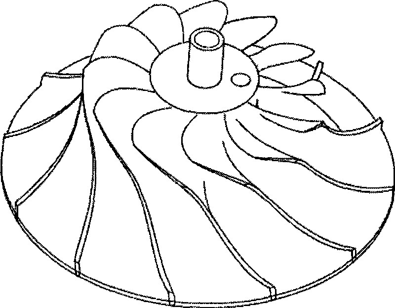
[0029] (1) Firstly, according to the possible deformation of SLM parts after hot isostatic pressing, three-dimensional modeling software (such as UG, Pro / E, etc.) is used to design the CAD three-dimensional model of the metal sheath before hot isostatic pressing. It is a shell with an opening, and a 1-2mm powder inlet hole is reserved on the cover. figure 2 It is the three-dimensional model of the impeller jacket with the powder inlet, and then processed by the slicing software and saved as an STL file, and the data information of the STL file is sent to the SLM rapid prototyping machine.

[0030] (2) Vacuum the forming chamber of the SLM rapid prototyping machine.

[0031] (3) The powder feeding mechanism spreads a layer of No. 45 steel powder with a thickness of 60 μm and a particle size of 20 μm on the working platform.

[0032] (4) Use diode-pumped YAG lasers, fiber lasers or CO2 lasers with a laser power greater than or equal to 100W, with a laser spot of 30 μm, a scann...


PUM

PropertyMeasurementUnit
thicknessaaaaaaaaaa
particle diameteraaaaaaaaaa

Abstract

The invention discloses an integral rapid manufacturing method of a hot isostatic pressing metal sheath, comprising the steps: (1) a CAD three-dimensional model of the metal sheath is designed by adopting three-dimensional molding software, and is then processed by slicing software and saved as an STL file, and the data information of the STL file is transmitted to an SLM rapid forming machine; (2) a forming chamber is vacuumized; (3) a metal powder layer is spread on a work platform flatly; (4) a semiconductor pumping YAG laser or a fiber laser is adopted to scan the metal powder positioned at the boundary of the slice layer, and the powder material at the boundary is melted; and (5) the step (3) and the step (4) are repeated until the compact sheath is manufactured. Powder inlet holes can be reserved on the sheath when designing the three-dimensional model of the sheath, so as to facilitate the subsequent processes such as powder filling, compaction by vibration, vacuum pumping and encapsulation. The sheath is compact and has a controllable shape, and can form parts with any complex shapes and structures, and can realize the high utilization rate of material.

Description

technical field [0001] The invention belongs to the field of parts forming and manufacturing, and in particular relates to an overall rapid manufacturing method of a hot isostatic pressing metal sheath. Background technique [0002] Hot isostatic pressing (HIP) is a process that uses high temperature and high pressure loads to realize the preparation of powder materials and the forming of parts. In particular, this technology can be used to realize the overall near net shape of precious metal powder parts such as ceramics, hard alloys, composite materials, titanium and nickel. The mechanical properties of the parts are equivalent to forgings of the same material, and the dimensional accuracy can reach 0.1mm. The utilization rate exceeds 90%, and there is almost no material waste. In this process, the forming material is in powder state, and the high-temperature and high-pressure medium is gas. In order to achieve the pressing effect of high temperature and high pressure ga...

Claims


Application Information

Patent Timeline
Patent Type & Authority Applications(China)
IPC IPC(8): B22F3/105
CPCB22F3/1055B22F3/15B33Y50/00B33Y40/00Y02P10/25B22F10/28B22F10/36B22F10/64B22F10/366B22F12/41
Inventor 史玉升魏青松曲兵兵杜艳迎刘洁
Owner HUAZHONG UNIV OF SCI & TECH
Why Eureka
Try Eureka