Composite current driving high pushing force density nine phase plane motor and driver thereof
A composite current, high thrust technology, applied in the direction of motor control, electric components, electrical components, etc., can solve the problems of small plane motion range, low winding utilization rate, low system efficiency, etc., to achieve large motion range, good dynamic characteristics, high efficiency effect
- Summary
- Abstract
- Description
- Claims
- Application Information
AI Technical Summary
Problems solved by technology
Method used
Image
Examples
specific Embodiment approach 1
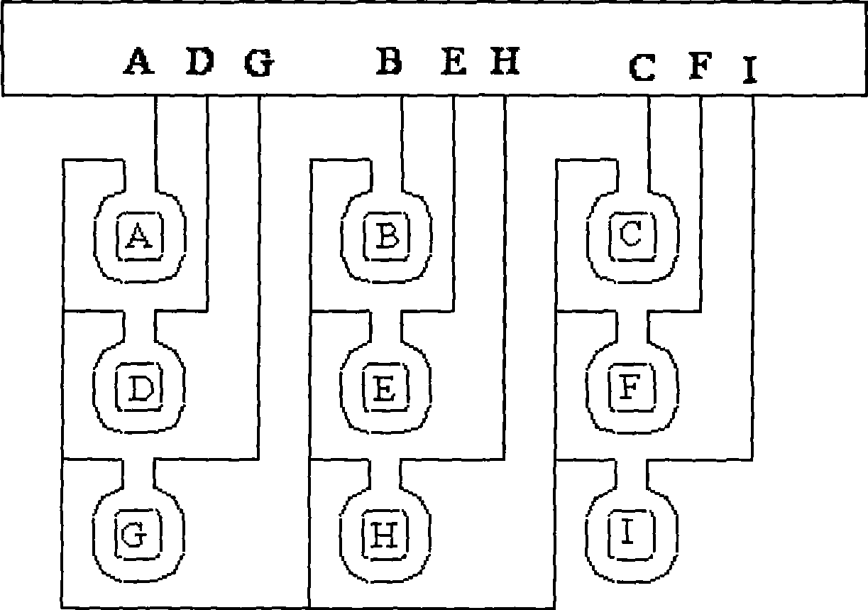
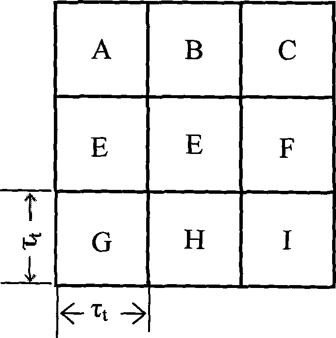
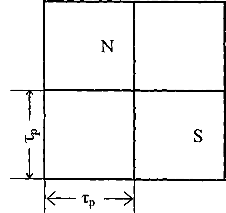
[0024] Specific Embodiment 1: The composite current-driven high thrust density nine-phase planar motor described in this embodiment includes an armature component and a permanent magnet excitation component. There is an air gap between the armature component and the permanent magnet excitation component, wherein the armature component includes Armature winding and armature core; permanent magnet excitation components including permanent magnet array and permanent magnet yoke plate; coil pitch τ in armature components t The pole distance τ of the permanent magnet array in the permanent magnet excitation part p Satisfy the relation 3nτ t =(3n±1)τ p , each planar motor is composed of i unit motors, each unit motor includes 9 coils and 2 permanent magnets, the 9 coils form a 3×3 matrix, each coil is a phase armature winding, a total of There are 9 phase armature windings, which are represented as; A phase, B phase, C phase, D phase, E phase, F phase, G phase, H phase, I phase ar...
specific Embodiment approach 2
[0025] Specific embodiment two: The composite current drive high thrust density nine-phase planar motor described in this embodiment includes an armature component and a permanent magnet excitation component, and an air gap is between the armature component and the permanent magnet excitation component, wherein the armature component includes Armature winding and armature core; permanent magnet excitation components including permanent magnet array and permanent magnet yoke plate; coil pitch τ in armature components t The pole distance τ of the permanent magnet array in the permanent magnet excitation part p Satisfy the relation 3nτ t =(3n±1)τ p , each planar motor is composed of i unit motors, each unit motor includes S coils and P permanent magnets, the P=2h 2 , S=9(m 2 +1) / 2; the flat permanent magnet yoke plate in each unit motor is evenly divided into 2h×2h permanent magnet cells, and the side length of the permanent magnet cells is the permanent magnet array pole pitc...
specific Embodiment approach 3
[0030] Specific implementation mode three: see Figure 4 , Figure 5 This embodiment will be described. This embodiment is an embodiment of the composite current-driven high thrust density nine-phase planar motor described in the second specific embodiment. This embodiment is composed of a motor unit, wherein m=3, h=4, n=3, and the motor has S = 45 coils and P = 32 permanent magnets, the coil distance τ in the armature assembly t The pole distance τ of the permanent magnet array in the permanent magnet excitation part p Satisfy the relation 9τ t =8τ p . see Figure 5 , since 3m and 2h are 9 and 8 respectively, which are coprime numbers, the flat permanent magnet yoke plate is evenly divided into 2h×2h permanent magnet unit cells, that is, 8×8 permanent magnet unit cells, and the 32 permanent magnets They are respectively fixed in the diagonally adjacent permanent magnet cells on the permanent magnet yoke plate, the permanent magnets are parallel or vertically non-adjace...
PUM
 Abstract
Description
Claims
Application Information
 - R&D
- Intellectual Property
- Life Sciences
- Materials
- Tech Scout
- Unparalleled Data Quality
- Higher Quality Content
- 60% Fewer Hallucinations
Browse by: Latest US Patents, China's latest patents, Technical Efficacy Thesaurus, Application Domain, Technology Topic, Popular Technical Reports.
© 2025 PatSnap. All rights reserved.Legal|Privacy policy|Modern Slavery Act Transparency Statement|Sitemap|About US| Contact US: help@patsnap.com


