High directional antenna using annular metal pair unit structure antenna cover

A technology of unit structure and radome, which is applied to antennas, antenna arrays, electrical components, etc., can solve problems such as inability to move freely, poor mobility, and poor directionality, and achieve narrow beam width, low load capacity, and reduced energy consumption. Effect

Inactive Publication Date: 2009-04-08
ZHEJIANG UNIV +1
View PDF0 Cites 15 Cited by
  • Summary
  • Abstract
  • Description
  • Claims
  • Application Information

AI Technical Summary

Problems solved by technology

[0006] In order to overcome the defects existing in the existing antenna, the object of the present invention is to provide a highly directional antenna using a ring-shaped metal pair unit structure radome, so that it can achieve the effect of improving gain and direc

Method used


Image

  • High directional antenna using annular metal pair unit structure antenna cover
  • High directional antenna using annular metal pair unit structure antenna cover
  • High directional antenna using annular metal pair unit structure antenna cover

Examples


Embodiment Construction

[0023] The present invention will be further described below with reference to the accompanying drawings and embodiments.

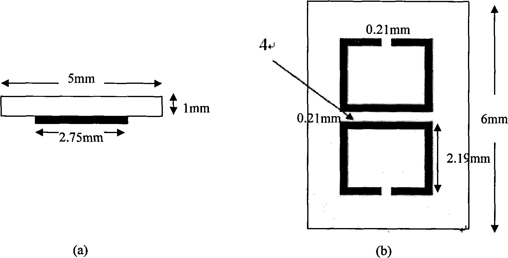
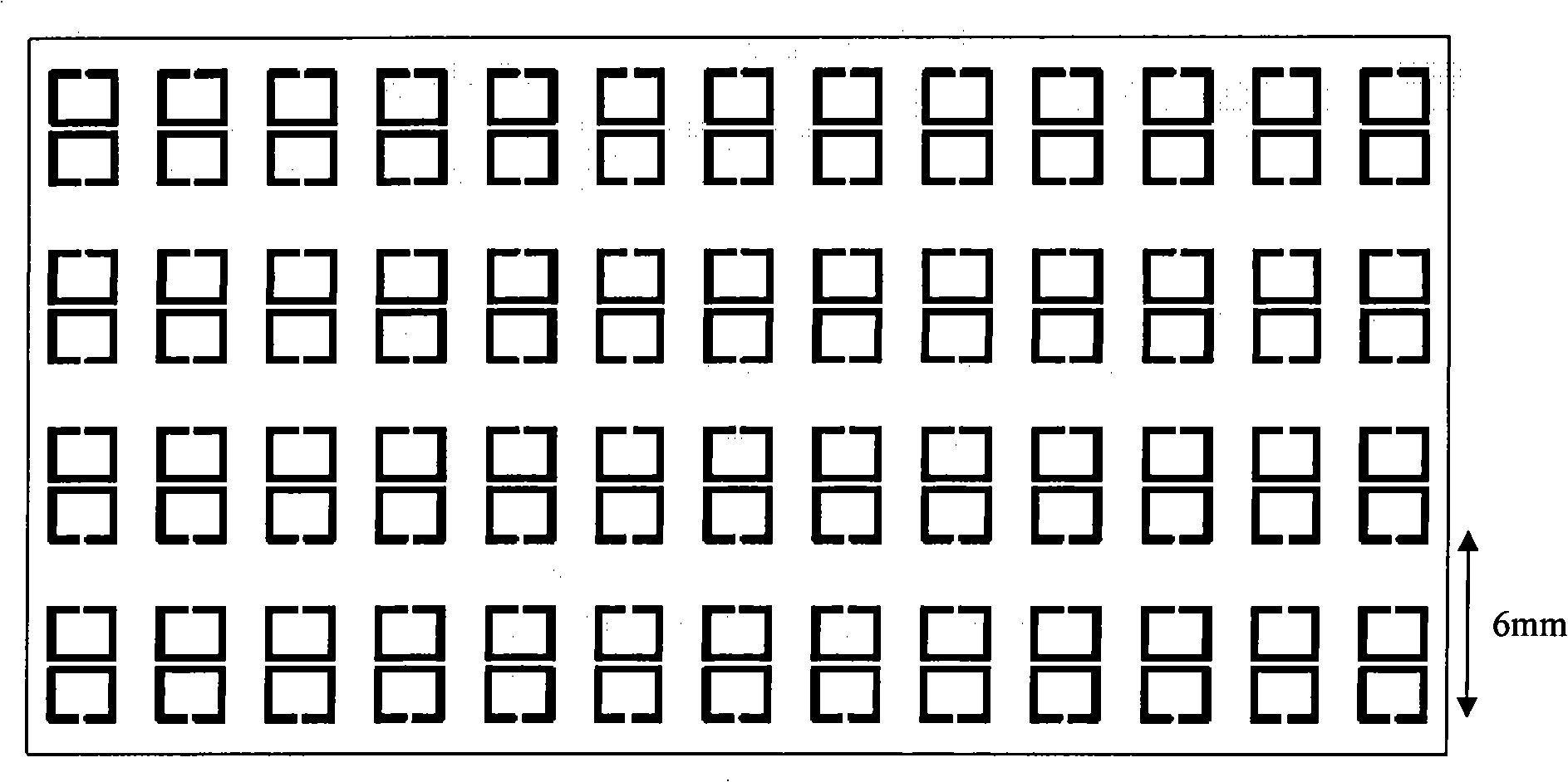
[0024] like figure 1 As shown, the present invention includes a microstrip antenna array 2 and 3-6 radomes 3, 3-6 radomes 3 and the microstrip antenna array 2 are arranged in parallel and equally spaced on the plexiglass base slot, and the microstrip antenna array 2 are installed in parallel and facing each other on the side of the radome 3 without the ring-shaped metal pair unit structure 4, and the distance between the microstrip antenna array 2 and the radome 3 is 5 mm.

[0025] like Figure 4 As shown, the microstrip antenna array 2: it is a microwave board with a dielectric constant of 2.65 and a thickness of 1mm, fed by an SMA connector 1, and connected to a 4×4 microstrip patch antenna through a microstrip line 5 Array 2, a total of 16 microstrip patch antennas 6, each microstrip patch antenna is a metal sheet of 11mm × 9mm, and the center distan...


PUM

PropertyMeasurementUnit
Thicknessaaaaaaaaaa

Abstract

The invention discloses a highly directional antenna utilizing a radome with the structure of ring-shaped metal pair units; the antenna comprises a microstrip antenna array, a feed source connected with the microstrip antenna array and the radome of sandwich type consisting of the structure of ring-shaped metal pair units. The structure of ring-shaped metal pair units manufactured on an FR4 printed circuit board is taken as the radome of the microstrip antenna array, the homotactic magnetic conductivity can be adjusted to be zero by changing the distance between the printed circuit boards, and the obtained corresponding effective index is zero. The energy of electromagnetic wave emitted by the microstrip antenna array can be concentrated along the normal direction of the radome when the electromagnetic wave passes through the radome, thus achieving the effect of accumulating energy and improving the directional property and the gain of the whole antenna. The highly directional antenna can be applied to various wireless transmissions, beam communications and interferential emission and receiving systems such as communication, radar, etc. Compared with the traditional antenna, the system structure of the antenna has the advantages of simple and small structure, convenient disassembly and assembly, low cost, good directional property, high gain, etc.

Description

technical field [0001] The invention relates to an antenna of a transmitting and receiving system in the field of wireless communication, in particular to a high-direction antenna using a ring-shaped metal pair unit structure radome. Background technique [0002] With the rapid development of high and new technology, the core supporting role of electronic technology in military and civilian use is becoming more and more obvious. In particular, modern warfare has exacerbated the confrontation in the electromagnetic field. The battlefield situation is changing rapidly, and information exchanges are more frequent. It is necessary to ensure smooth communication at any time. Therefore, it is particularly important to have powerful anti-jamming communication and communication interference tools. In civilian use, mobile communication is a very popular technology application in today's society, and mobile phones have become an essential communication tool for people. [0003] In v...

Claims


Application Information

Patent Timeline
IPC IPC(8): H01Q21/00H01Q13/08H01Q19/00
Inventor 姜涛王志宇彭亮皇甫江涛冉立新崔万照马伟
Owner ZHEJIANG UNIV
Why Eureka
Try Eureka