System for monitoring transforming plant DC

A DC monitoring and substation technology, applied in general control systems, control/regulation systems, non-electrical signal transmission systems, etc., can solve problems such as heavy tasks, unreachable data, data transmission delays, etc., to reduce the burden and reduce equipment replacement. , the effect of improving openness and compatibility

Inactive Publication Date: 2009-04-22
HEBI POWER SUPPLY OF HENAN ELECTRIC POWERCORP
View PDF0 Cites 4 Cited by
  • Summary
  • Abstract
  • Description
  • Claims
  • Application Information

AI Technical Summary

Problems solved by technology

However, when establishing a set of DC remote monitoring and management system to monitor the DC operating power supplies of many substations or substations, it is necessary to ensure the efficiency of network data transmission, so as to ensure the timeliness of monitoring. When there are too many online data upload nodes, the amount of data When it is too large, the tasks of online data processing and transmission nodes are heavy, which often causes delays in data transmission. If there is a failure of online data processing and transmission nodes, it will cause the data of all data upload nodes to fail to reach the centralized monitoring center
Finally, most of the DC equipment in the current substation is equipped with battery inspection and insulation detection devices. These devices and devices themselves have digital interfaces, but the equipment in each substation may come from different manufacturers, so integrating and transmitting these data has become an urgent problem to be solved. problem; at the same time, in the substation using high-frequency switching power supply, the data collection in the station mainly depends on the microcomputer DC monitor used in the original system; it can be seen that how the function of the microcomputer DC monitor used in the original system is too weak or does not have the microcomputer DC monitor It is also a problem to be solved to realize remote centralized monitoring of DC

Method used


Image

  • System for monitoring transforming plant DC
  • System for monitoring transforming plant DC
  • System for monitoring transforming plant DC

Examples


Embodiment Construction

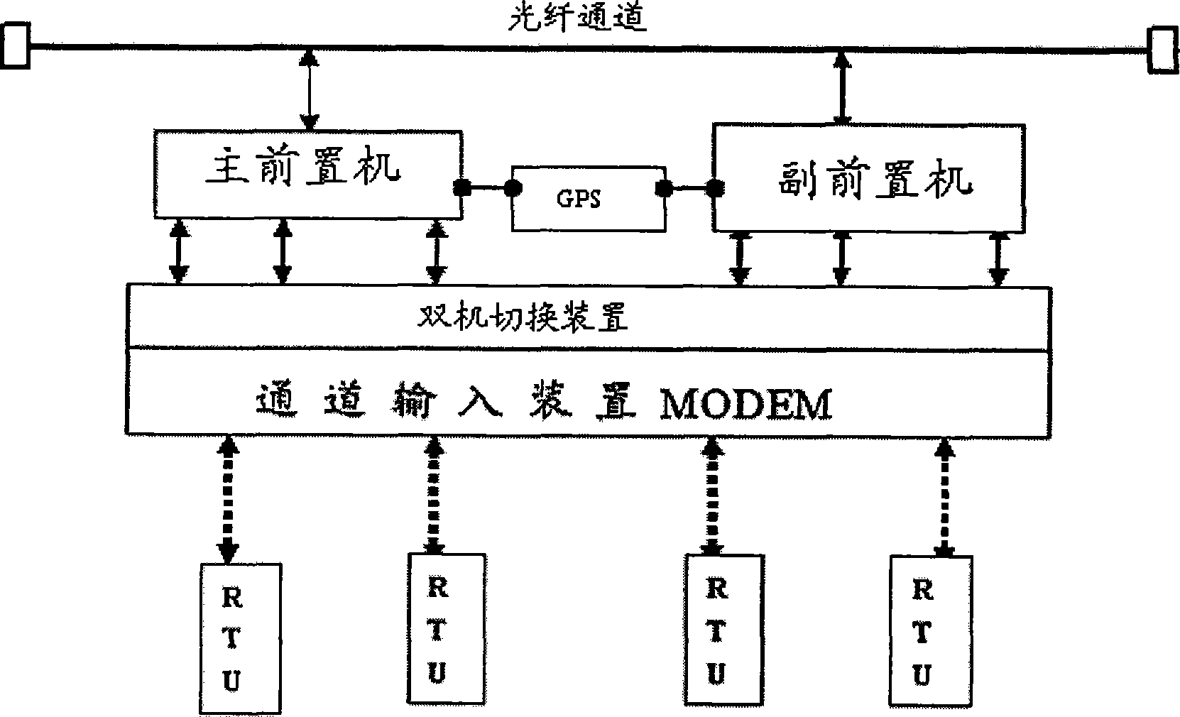
[0016] During specific implementation, the present invention includes remote measurement and control unit (RTU), fiber channel input unit, fiber channel, server, workstation and client computer; Fiber channel input unit is connected with remote measurement and control unit and fiber channel respectively, server, workstation and The client computers are respectively connected to the fiber channel; the connection and related system software presets can refer to the existing data acquisition and monitoring control system (SCADA system).

[0017] Such as figure 1 As shown, the front-end processor of the present invention is arranged between the fiber channel input device MODEM and the fiber channel. The dual-computer switching device is connected to the fiber channel input unit, the main front-end processor and the auxiliary front-end processor are connected to the dual-computer switching device, and the communication method between the main front-end processor and the auxiliary f...


PUM


Abstract

The present invention discloses a transformer DC monitoring system, which consists of a far-end measurement control unit, an optical fiber channel input unit, an optical fiber channel, a server, a workstation and a client. A prepositive computer is arranged between the optical fiber channel input unit and the optical fiber channel; the prepositive computer consists of a main prepositive computer, a deputy prepositive computer and a dual-computer switching device; the dual-computer switching device is connected with the optical fiber channel input unit; the main prepositive computer and the deputy prepositive computer are both connected with the dual-computer switching device; the communication mode between the main prepositive computer and the deputy prepositive computer adopts GPS wireless mode; data monitoring, parameter setting, data analog, data pre-treatment and data transmission computer programs are arranged in the main prepositive computer and the deputy prepositive computer in advance. The transformer DC monitoring system makes full use of existing equipment to establish a long-distance centralized DC monitoring system which is applicable to various substations and improve the comprehensive monitoring level, openness and expandability of the system and the stability and reliability of the monitoring. The transformer DC monitoring system is used for power systems.

Description

technical field [0001] The invention relates to the technical field of comprehensive automation management of electric power systems, in particular to a DC monitoring system for substations. Background technique [0002] The DC operating power system is one of the indispensable secondary equipment in the substation, and its reliability directly affects the safe and reliable operation of the equipment in the substation. The application of a large number of microcomputer protection devices and comprehensive automation equipment, as well as the adoption of valve-regulated sealed lead-acid batteries, have higher and higher requirements for DC operating power supplies. However, the current DC management and operation are basically still the original management methods and models, and it is difficult to meet the requirements of integrated automation and unattended stations for DC systems. The current operation monitoring is all in the dispatching center or centralized control sta...

Claims


Application Information

Patent Timeline
IPC IPC(8): H02J11/00H02J13/00G05B15/02G08C23/06G06F15/163
CPCY04S10/30Y02E60/723Y04S40/126Y04S40/124Y04S40/143Y02E60/7838Y02E60/7884Y02E60/7853Y04S10/16Y02E60/74Y02E60/00Y04S20/00Y02B90/20
Inventor 申润田张爱国郝建刚武玉丰邵利坤
Owner HEBI POWER SUPPLY OF HENAN ELECTRIC POWERCORP
Why Eureka
Try Eureka