Turbocharger
A turbocharger and turbine technology, applied in the direction of machines/engines, engine components, mechanical equipment, etc., can solve the problems of high price, fragile, complex structure, etc., to improve the responsiveness of the turbine, improve efficiency, and simple structure. Effect
- Summary
- Abstract
- Description
- Claims
- Application Information
AI Technical Summary
Problems solved by technology
Method used
Image
Examples
Embodiment 1
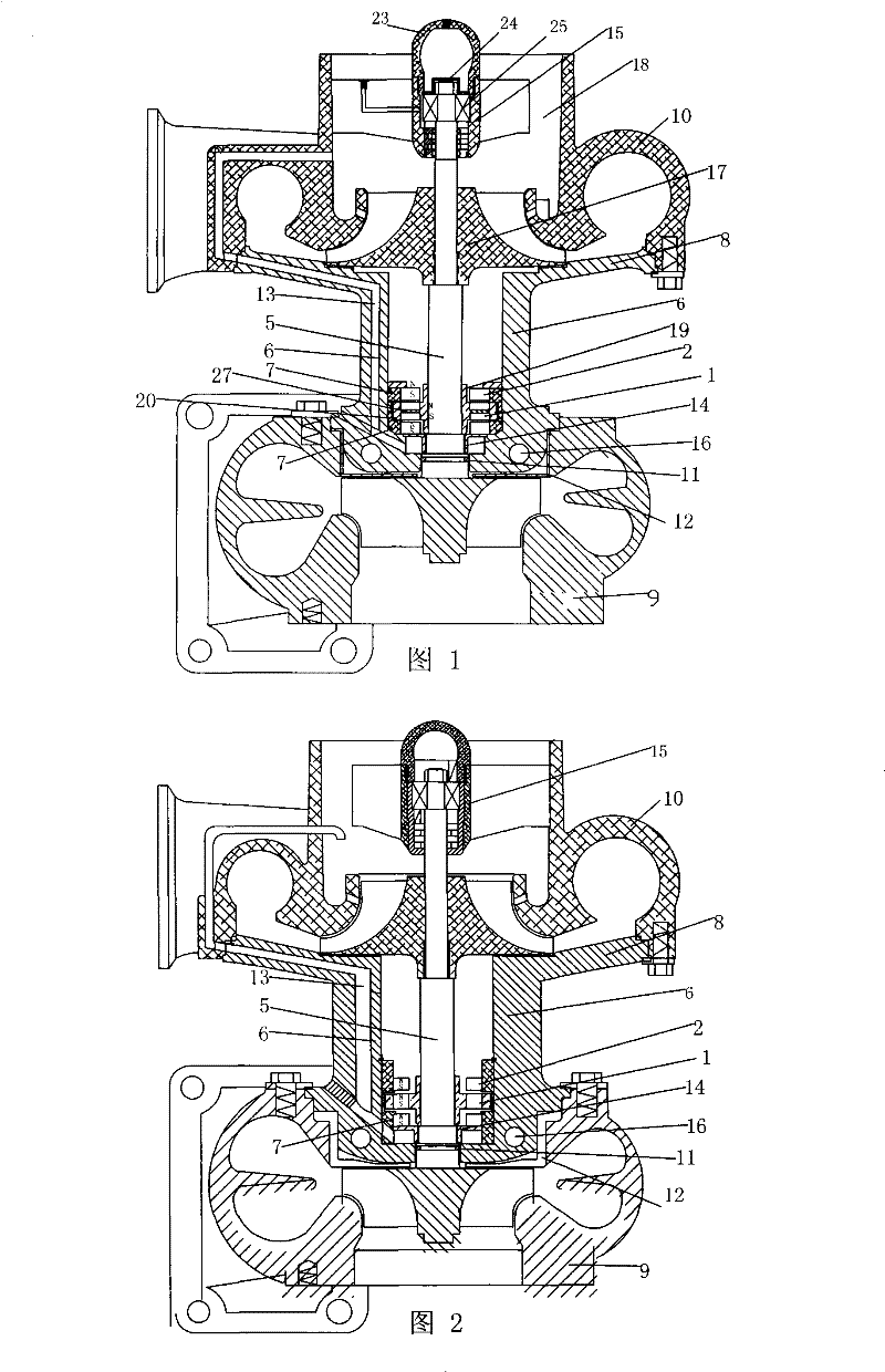
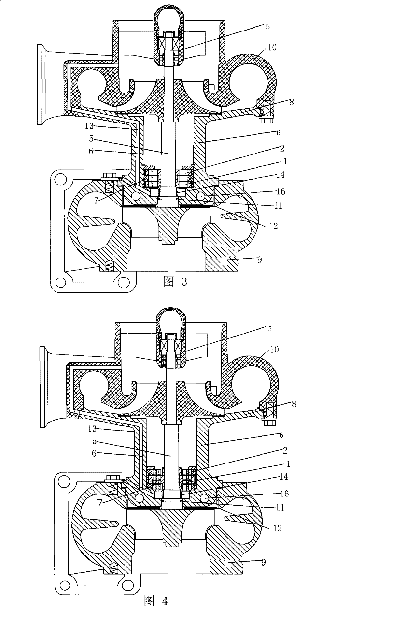
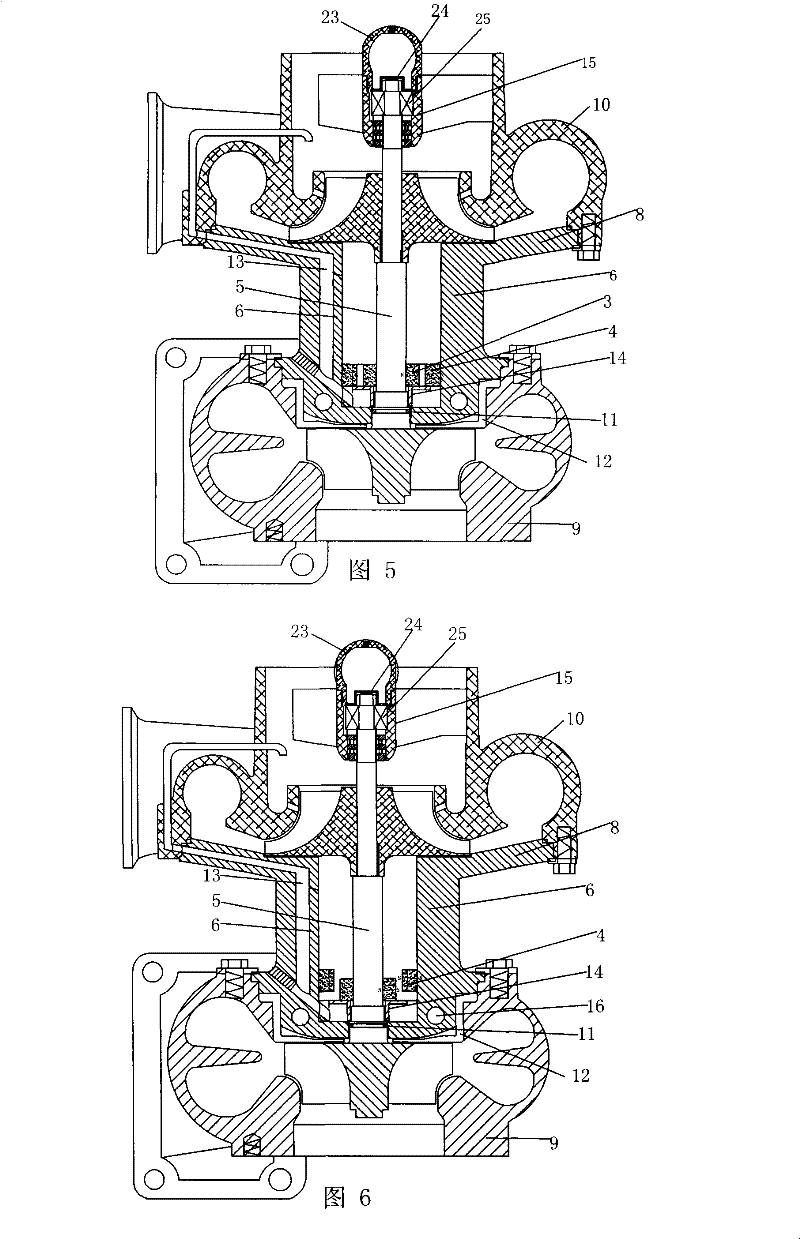
[0024] A turbocharger, such as the attached figure 1 As shown, it includes a turbine rotor shaft assembly 5, an intermediate body 6, a compressor impeller 17, a turbine casing 9, a pressure casing 10, an air inlet 18, a diffuser plate 8 made integrally with the pressure casing 1, and a turbine rotor shaft assembly 5 includes the rotor shaft, the turbine installed on the rotor shaft and the compressor impeller 17, on the turbine rotor shaft assembly 5, a set of permanent magnetic rings that cooperate with each other are installed between the turbine and the compressor impeller 17, and the permanent The magnetic magnetic ring includes two permanent magnet moving magnetic rings and two permanent magnet static magnetic rings, the two permanent magnet moving magnetic rings 1 are arranged adjacently, and a magnetic guide sleeve 27 is installed between the two axial directions, so that the two permanent magnets The moving magnetic ring is positioned on the non-conductive magnetic sle...
Embodiment 2
[0029] Such as figure 2 As shown, the difference between this embodiment and Implementation 1 is mainly that a set of mutually matched permanent magnet rings installed between the turbine and the compressor impeller 17 is an axial polarity permanent magnet ring, which includes a permanent magnet A moving magnet ring 1 and two permanent magnet static magnet rings 2, the two sides of the permanent magnet moving magnet ring 1 are respectively provided with a permanent magnet static magnet ring 2, the permanent magnet moving magnet ring 1 and the permanent magnet static magnet ring 2 cooperate to make the turbine The turbine end of the rotor shaft assembly 5 is suspended. The specific structure of the cooling method is different, mainly in that the cooling channel 13 makes the compressed air entering the vortex end bearing cavity flow back to the air inlet through the air duct.
Embodiment 3
[0031] Such as image 3 As shown, the difference between this embodiment and Implementation 1 is mainly that a group of mutually matched permanent magnet rings installed between the turbine and the compressor impeller 17 is an axial polarity permanent magnet ring, which includes two permanent magnet rings. A magnetic moving magnet ring 1 and a permanent magnet static magnet ring 2, the permanent magnet moving magnet ring 1 is located on both sides of the permanent magnet static magnet ring 2 and arranged axially along the rotor shaft.
PUM
 Abstract
Description
Claims
Application Information
 - R&D
- Intellectual Property
- Life Sciences
- Materials
- Tech Scout
- Unparalleled Data Quality
- Higher Quality Content
- 60% Fewer Hallucinations
Browse by: Latest US Patents, China's latest patents, Technical Efficacy Thesaurus, Application Domain, Technology Topic, Popular Technical Reports.
© 2025 PatSnap. All rights reserved.Legal|Privacy policy|Modern Slavery Act Transparency Statement|Sitemap|About US| Contact US: help@patsnap.com


