High-frequency transformer of spot welding machine

A high-frequency transformer and spot welding machine technology, applied in the field of transformers, can solve the problems of large loss, large loss, and temperature rise of the transformer, and achieve the effects of reducing copper circuit loss, reducing leakage inductance, and reducing volume

Active Publication Date: 2009-05-13
SHENZHEN HONGBAI TECH IND
View PDF0 Cites 14 Cited by
  • Summary
  • Abstract
  • Description
  • Claims
  • Application Information

AI Technical Summary

Problems solved by technology

However, due to the limitations of electronic devices, high-frequency transformer materials, and manufacturing processes, the distribution parameters of high-frequency transformer capacitance and inductance are large, the loss is large, especially the leakage inductance is large, and the voltage output current is limited when the voltage is low, so it is impossible to improve the transformer. output power
Although the emergence of soft-switching power supplies has reduced the manufacturing process requirements of transformers, the stress requirements on IGBTs are still too high, but there are still limitations in output power at low voltages.
At the same time, the loss of the transformer is too large, and it is difficult for the high-frequency transformer to dissipate heat. With the increase of the output power, the temperature rise of the transformer is very high, and it is difficult to increase the output power.
At present, the high-frequency transformer of the spot welding machine has a large volume and low power, and the output power is only below 10KW, which cannot meet the high-current and high-power requirements of the high-frequency transformer of the spot welding machine for the spot welding machine.

Method used


Image

  • High-frequency transformer of spot welding machine
  • High-frequency transformer of spot welding machine
  • High-frequency transformer of spot welding machine

Examples


Embodiment Construction

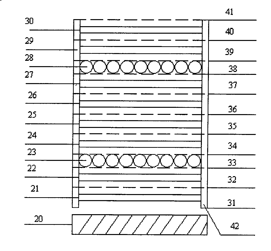
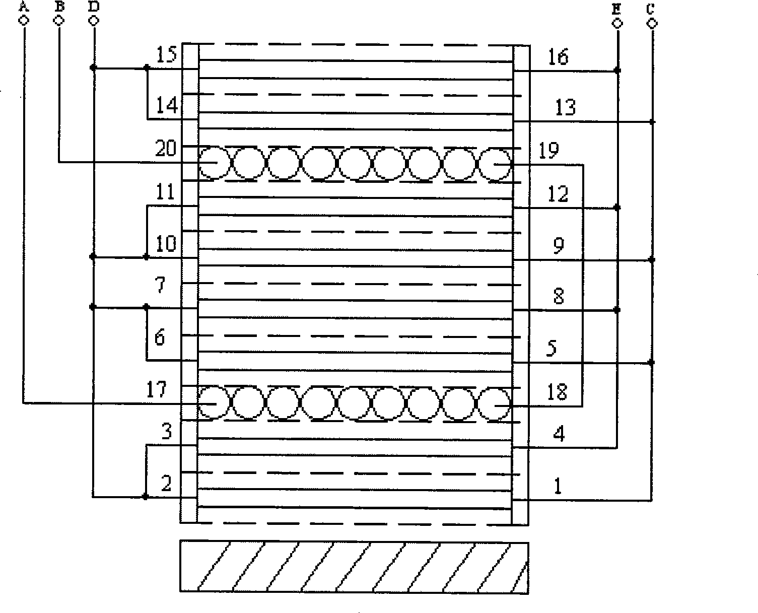
[0018] The guiding ideology of the present invention is: reduce the leakage inductance of the transformer, which can reduce the requirements for IGBT stress and improve the output power; reasonable selection of materials, strict manufacturing process, to ensure the consistency of transformer parameters, such as transformer inductance, leakage inductance, The difference in parameters such as the air gap is not greater than (0.5-2%), and the effective parallel connection of multiple transformers is achieved, thereby achieving the purpose of increasing the output power rate. Effectively handle the heat dissipation problem of the transformer's lead legs and improve the duty cycle of the transformer. Concrete practice of the present invention is:

[0019] ① Select the appropriate magnetic core according to the size of the output power, usually the EE type magnetic core is easy to reduce the leakage inductance;

[0020] ②The primary section and the secondary winding are alternately...


PUM

PropertyMeasurementUnit
diameteraaaaaaaaaa
thicknessaaaaaaaaaa
thicknessaaaaaaaaaa

Abstract

The invention discloses a high-frequency transformer used for a spot welding machine, comprising a magnetic core, primary coils and secondary coils; the primary coil and the secondary coil are alternatively wound by layer; an insulation layer is arranged between two adjacent layers; the primary coil is laminated between two primary coil layers; the internal layer and the external layer of the primary coil layer are provided with the secondary coil layers; the secondary coil is wound by thin copper strip layer by layer with one turn for each layer. The structure of the high-frequency transformer is convenient for the winding of the transformer, reduces the volume, weight, inductance leakage and loss of the copper passage, is convenient for educing the secondary heat, and is beneficial for the high-frequency transformer to output larger current and higher power.

Description

[technical field] [0001] The invention relates to a transformer, in particular to a high-frequency transformer used by a spot welding machine. [Background technique] [0002] Traditional resistance welding power sources are mainly AC and DC power frequency spot welding machines, which control the welding current by adjusting the conduction angle of the thyristor. The technology is relatively mature, but the volume is huge. Because it is a single-phase input, the energy consumption is high, the efficiency is low, the dynamic performance is poor, and the control precision is not high. [0003] In the 1980s and 1990s, intermediate frequency inverter resistance welding appeared, the power supply was upgraded from the original single-phase to three-phase, and the operating frequency of the transformer was increased from 50HZ to about 1000HZ. The volume of the medium frequency resistance welding machine is greatly reduced, and the efficiency is also improved. The welding efficie...

Claims


Application Information

Patent Timeline
Patent Type & Authority Applications(China)
IPC IPC(8): H01F27/28H01F27/24H01F27/29
Inventor 韩玉琦陈志伟戴建明任再祥龙立新韩东
Owner SHENZHEN HONGBAI TECH IND
Why Eureka
Try Eureka