Method for detecting rotor position in non position sensor switch magnetic resistance motor

A switched reluctance motor, rotor position technology, applied in devices using electric/magnetic methods, electronic commutation motor control, electrical components, etc., can solve problems such as increasing motor output torque fluctuations and reducing motor system efficiency. , to achieve the effect of reducing manufacturing cost and process, convenient detection of rotor position, and increasing torque fluctuation

Inactive Publication Date: 2009-05-20
HARBIN INST OF TECH
View PDF0 Cites 37 Cited by
  • Summary
  • Abstract
  • Description
  • Claims
  • Application Information

AI Technical Summary

Problems solved by technology

[0005] The purpose of the present invention is to solve the problem that the existing method of indirectly detecting the rotor position causes resistance torque an

Method used


Image

  • Method for detecting rotor position in non position sensor switch magnetic resistance motor
  • Method for detecting rotor position in non position sensor switch magnetic resistance motor
  • Method for detecting rotor position in non position sensor switch magnetic resistance motor

Examples


specific Embodiment approach 1

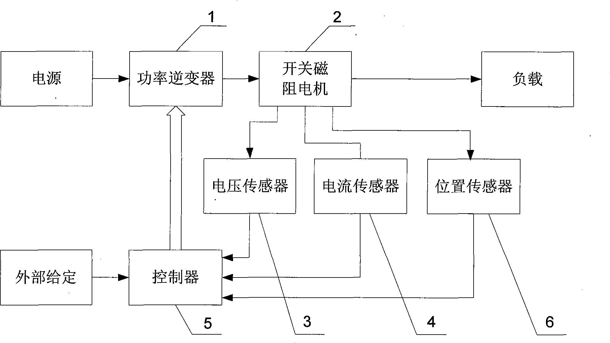
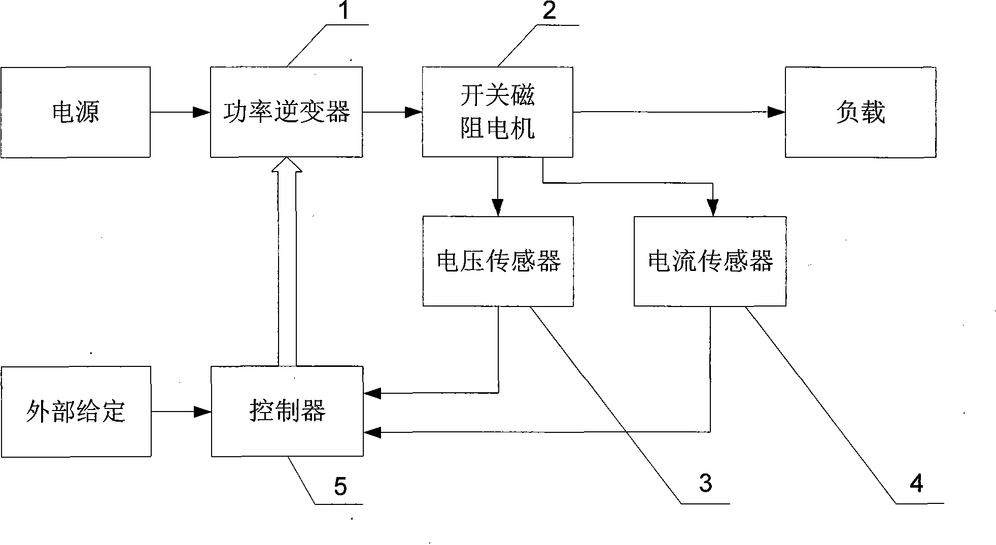
[0012] Specific implementation mode one, the following combination figure 2 , image 3 This embodiment is described. The device for implementing the method of this embodiment includes a power inverter 1, a switched reluctance motor 2, a voltage sensor 3, a current sensor 4, and a controller 5. The phase winding adopts chopper current closed-loop control. The method includes:

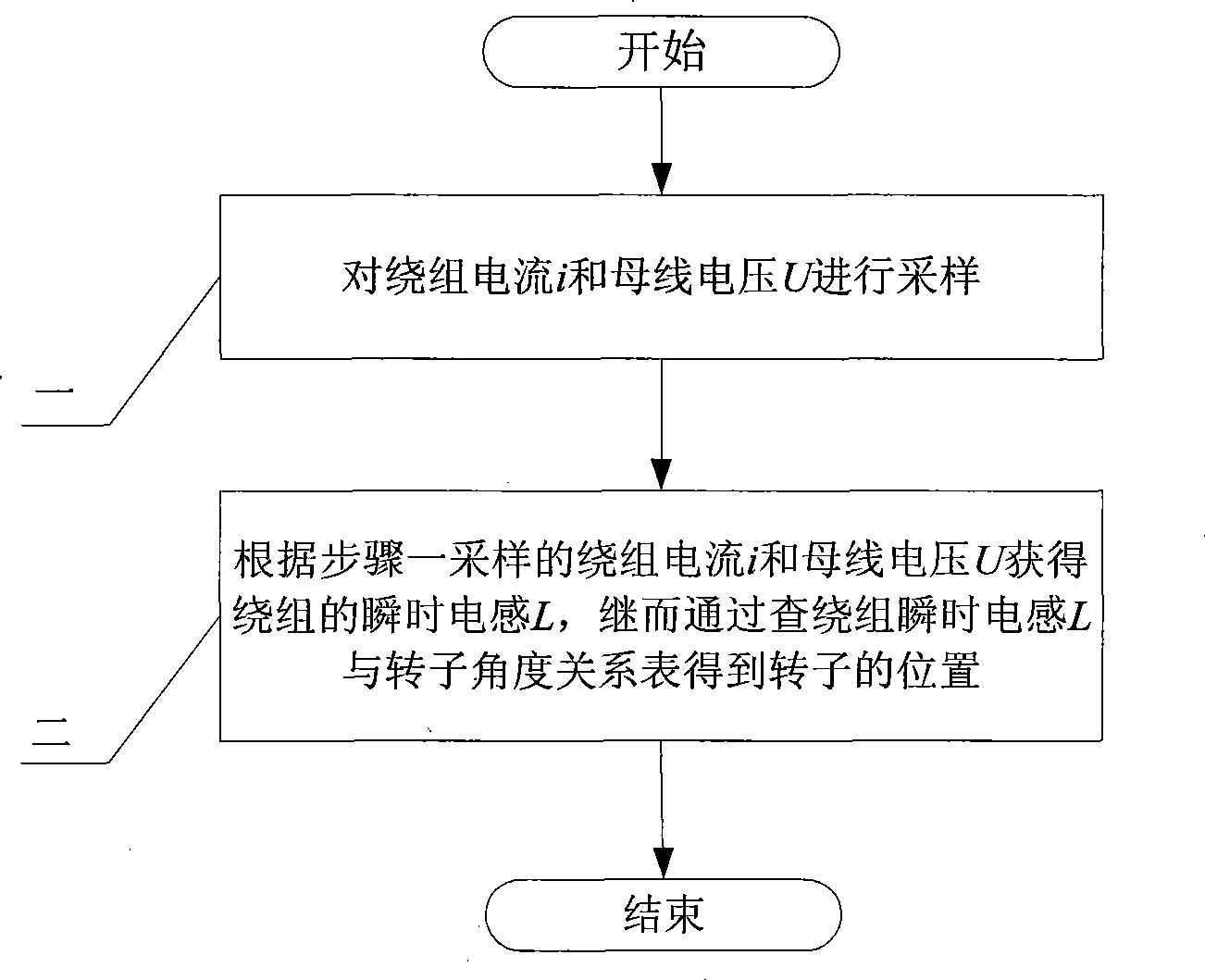
[0013] Step 1. Sampling the winding current i and the bus voltage U: the controller 5 samples the winding current i of the switched reluctance motor 2 measured by the current sensor 4 , and at the same time, the controller 5 samples the switched reluctance motor 2 measured by the voltage sensor 3 2 bus voltage U for sampling;

[0014] Step 2: Obtain the instantaneous inductance L of the winding according to the winding current i sampled in step 1 and the bus voltage U, and then obtain the position of the rotor by checking the relationship table between the instantaneous inductance L of the winding and ...

specific Embodiment approach 2

[0018] Specific implementation mode two, the following combination Figure 4 , Figure 5 Describe this embodiment. The difference between this embodiment and Embodiment 1 is that the method for obtaining the instantaneous inductance L of the winding is:

[0019] The power tube of power inverter 1 is turned on, so that when the winding current i is in the rising phase, according to the formula

[0020] i ( t ) = U - U 1 R + ( i 0 - U - U 1 R ) e - R L t

[0021] Find the instantaneous i...

specific Embodiment approach 3

[0039] Specific implementation mode three, the following combination Figure 6 Describe this embodiment. The difference between this embodiment and Embodiment 1 is that the method for obtaining the relationship table between the instantaneous inductance L of the winding and the rotor angle is as follows: fix the motor rotor at a set angle, pass 50Hz alternating current into the winding, and measure Winding voltage U 2 and current I 2 , using the formula

[0040] 2 π × 50 × L = ( U 2 I 2 ) 2 - R 2

[0041] Calculate the instantaneous inductance L of the winding at the angular position of the rotor, where R is the eq...


PUM


Abstract

The invention provides a method for detecting rotor position of a switch reluctance motor without a position sensor, and belongs to the field of motor control. The invention aims at solving the problems existing in the prior method for indirectly detecting the rotor position that resisting moment and moment harmonic components occur in the motor rotor so that the efficiency of a motor system is reduced. The method comprises the following steps: 1, winding current i and busbar voltage U are sampled; and 2, according to the winding current in step one, instantaneous inductance (L) of the winding is acquired, and by looking up the winding instantaneous inductance (L) and rotor angle relation table, the rotor position is acquired. The method can lower manufacturing process of the switch reluctance motor, and has good application prospect in oil fields, coal mines, elevators, home appliances and the like.

Description

technical field [0001] The invention relates to a rotor position detection method of a switched reluctance motor without a position sensor, belonging to the field of motor control. Background technique [0002] The existing switched reluctance motor drive system (SRD) such as figure 1 As shown, the system consists of a power inverter 1 with a power tube and its drive module, a switched reluctance motor 2, a voltage sensor 3 for measuring the DC bus voltage, a current sensor 4 for measuring the winding current, a controller 5 and a motor rotor position measurement The position sensor 6 is composed of. According to the "minimum reluctance principle", the stator poles interact with the rotor poles to generate torque by sequentially energizing the stator excitation windings, so the SRD has a simple structure and reliable operation. [0003] The operation of SRD requires online real-time detection of feedback quantities, such as rotor position, speed and current, etc., and then...

Claims


Application Information

Patent Timeline
IPC IPC(8): H02P6/18G01P3/44H02P6/182
Inventor 吴红星寇宝泉贵献国刘奉海侯云鹏
Owner HARBIN INST OF TECH
Why Eureka
Try Eureka