Device and method for extracting light clock

A clock extraction and clock signal technology, applied in optical fiber transmission, coupling of optical waveguides, electromagnetic wave transmission systems, etc., can solve the problems of limited clock extraction range, high process difficulty, and high device power consumption, avoiding excessive loss of time, Achieving power balance, achieving simple effects

Inactive Publication Date: 2009-05-20
UNIV OF ELECTRONICS SCI & TECH OF CHINA
View PDF0 Cites 14 Cited by
  • Summary
  • Abstract
  • Description
  • Claims
  • Application Information

AI Technical Summary

Problems solved by technology

Generally speaking, SOA-based solutions (MZI-SOA or ultra-long SOA) are mostly researched in the world, but MZI-SOA may have the problems of complex control and high power consumption of devices; the cost of optical phase-locked loop technology is high, and High power consumption; using fiber ring mode-locked laser for clock recovery can obtain a higher rate clock signal, but its stability is poor, and the volume is relatively large; the clock recovery technology based on multi-zone DFB laser self-pulsation has high transmission rate, The device has the advantages of small size, high integration and low power consumption, but the manufacturing process of the device is relatively difficult; relatively speaking, the clock recovery technology using the Fabry-Perot filter has high-speed working potential and simple structure advantages, but it has problems such as clock drift, limited range of extractable clocks, etc.

Method used


Image

  • Device and method for extracting light clock
  • Device and method for extracting light clock
  • Device and method for extracting light clock

Examples


Embodiment 1

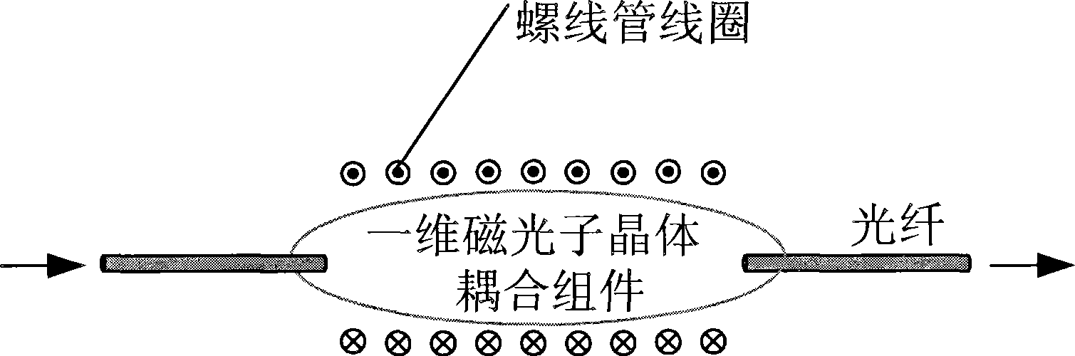
[0063] Embodiment 1 uses a solenoid coil to provide an external magnetic field for the one-dimensional magnetophotonic crystal fiber coupling component, and the magnetic field application method is as follows image 3 .

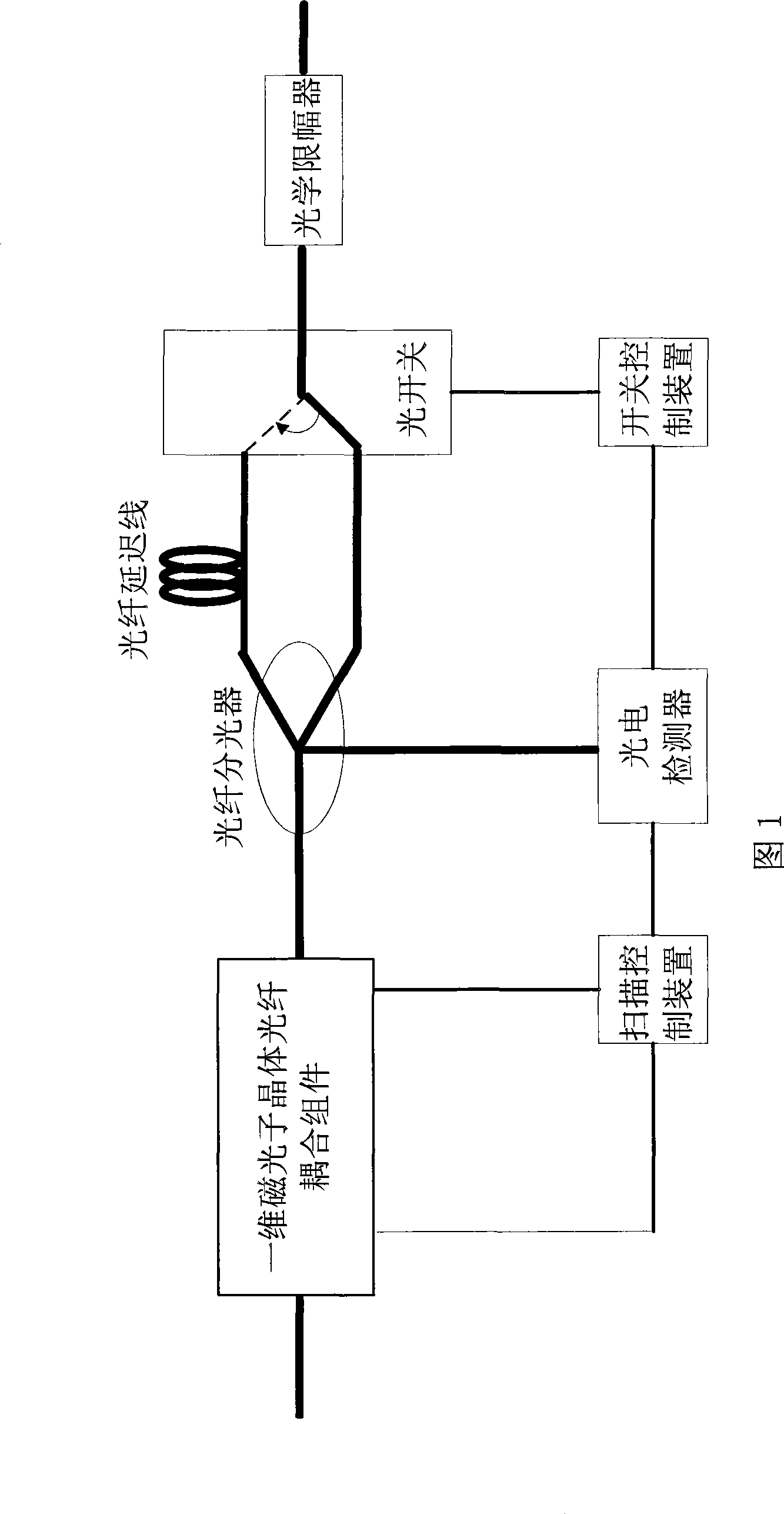
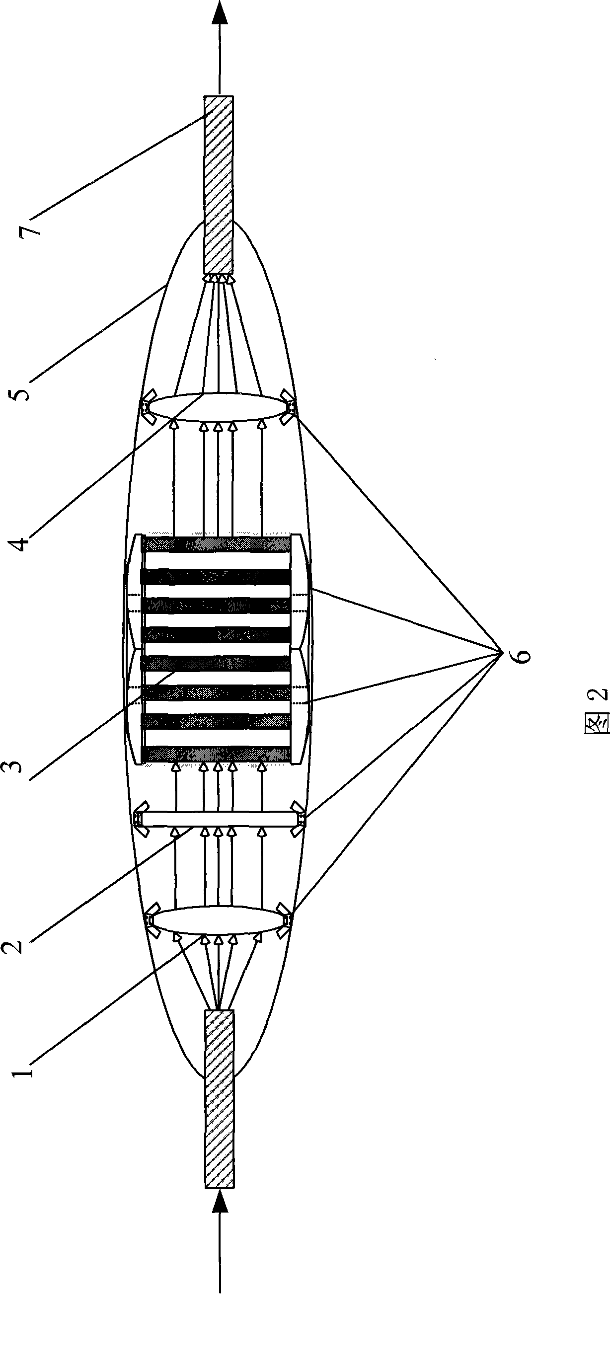
[0064] The center frequency of the signal light input is 1550nm, which is provided by a tunable laser light source. It is characterized by the fine adjustment of the wavelength, the adjustable range is 2nm, the output power is adjustable from 0 to 10mW, and the C-band wavelength scan is from 1527nm to 1565nm. After the signal light is generated by the adjustable laser light source, it enters the one-dimensional magneto-photonic crystal fiber coupling component through the optical fiber for optical filtering, that is, the optical clock signal is extracted, and the external magnetic field is adjusted here to affect the transmission spectrum of the one-dimensional magneto-photonic crystal. The distance between the two transmission resonant peaks is such that the ...

Embodiment 2

[0080] like Figure 4 , The difference between Embodiment 2 and Embodiment 1 lies in the way of applying a magnetic field. In Embodiment 1, a solenoid coil is used to provide an external magnetic field for the one-dimensional magnetophotonic crystal fiber coupling component, and in this embodiment, a combination of a permanent magnetic pole device and a solenoid coil is used to provide an external magnetic field to change the one-dimensional magnetophotonic The transmission spectrum of the crystal adjusts the distance between two transmission resonance peaks, so that the optical clock can be extracted normally.

Embodiment 3

[0082] like Figure 5 As shown, the difference between Embodiment 3 and Embodiment 1 lies in that the external magnetic field of the one-dimensional magneto-photonic crystal fiber coupling component is different. In embodiment 1, the external magnetic field is provided by the solenoid coil to realize the adjustment of the external magnetic field; in this embodiment, the adjustment of the external magnetic field is realized by changing the direction of the magnetic poles, thereby changing the transmission spectrum of the one-dimensional magnetophotonic crystal and adjusting the two transmission The distance between the formants allows the optical clock to be extracted normally.


PUM


Abstract

The invention discloses an optical clock extractor, which belongs to the technical field of optical communication and solves the problems that in the prior art, the optical clock extractor is complex and the extractable clock range thereof is limited. The optical clock extractor comprises a one-dimensional magnetic photonic crystal optical fiber coupler module and an adjustable off-set magnetic field unit for providing an applied magnetic field for the one-dimensional magnetic photonic crystal optical fiber coupler module, wherein the one-dimensional magnetic photonic crystal optical fiber coupler module comprises a collimating lens, a polarizer, a one-dimensional magnetic photonic crystal and a self-focusing lens. The invention also provides a method for performing optical clock extraction by using the extractor, which can achieve the adjustment of the spacing between transmission harmonic peaks to finally realize the optical clock extraction and process optical clock signals into the required forms. The optical clock extractor and the method not only achieve the optical clock extraction, but also can inhibit the jitter of the optical clock signals in the transmission process, and have the characteristics of simple realization, low cost, convenient operation, and automatic recognition of optical signal clocks.

Description

technical field [0001] The invention relates to an optical clock signal extraction device and method thereof, in particular to a device and method for extracting optical clock signals by using one-dimensional magneto-photonic crystals. Background technique [0002] In an actual optical network, optical signals need to pass through a certain number of optical amplifiers and long-distance optical fibers. The noise accumulation and nonlinear properties of these components degrade the signal quality, so signal regeneration is required. All-light regeneration is the most ideal way of light regeneration. All-optical reamplification, retiming, and reshaping (3R) technology is an important technology for realizing all-optical communication. [0003] When designing an all-optical signal processing system in an all-optical communication system, such as an optical regeneration system, an optical time division multiplexing system, an optical demultiplexer, and an all-optical switch, th...

Claims


Application Information

Patent Timeline
Patent Type & Authority Applications(China)
IPC IPC(8): H04B10/17G02B6/32G02B6/26H04B10/25
Inventor 武保剑魏锦哲邱昆
Owner UNIV OF ELECTRONICS SCI & TECH OF CHINA
Why Eureka
Try Eureka