Cleaner for CMP equipment grinding head

A technology for cleaning devices and grinding heads, which is applied in the direction of grinding devices, grinding/polishing safety devices, grinding machine tools, etc., and can solve the threat of surface flatness and state of silicon wafer products, affecting the yield of silicon wafer products, micro-scratches, etc. problems, to achieve the effect of reducing the possibility of excessive particles and product scratches, reducing the time and frequency of maintenance and cleaning, and preventing crystallization and agglomeration

Inactive Publication Date: 2009-05-27
SHANGHAI HUA HONG NEC ELECTRONICS
View PDF0 Cites 11 Cited by
  • Summary
  • Abstract
  • Description
  • Claims
  • Application Information

AI Technical Summary

Problems solved by technology

Because the acidic or alkaline grinding liquid used in CMP equipment is easy to form crystals, if it is not washed in time, a large number of liquid crystals will be adsorbed on the surface of the large peripheral area 43 of the grinding head within one maintenance frequency. When the head or itself moves, these massive adsorbents may fall on the polishing pad at any time, thus posing a great threat to the surface flatness and state of silicon wafer products, and ultimately affecting the yield of silicon wafer products
[0005] The usual solution now is that the operator does cleaning and maintenance every two weeks. During maintenance, the condensation on the surface of the large area around the grinding head 43 is scraped off, but this maintenance is time-consuming and laborious, and the effect is not good. Cleaning will make the grinding The surface around the head becomes rougher and more likely to form condensation in the future, which is likely to cause excessive particles and micro-scratches, which is not conducive to the long-term continuous operation of CMP equipment

Method used


Image

  • Cleaner for CMP equipment grinding head
  • Cleaner for CMP equipment grinding head
  • Cleaner for CMP equipment grinding head

Examples


Embodiment Construction

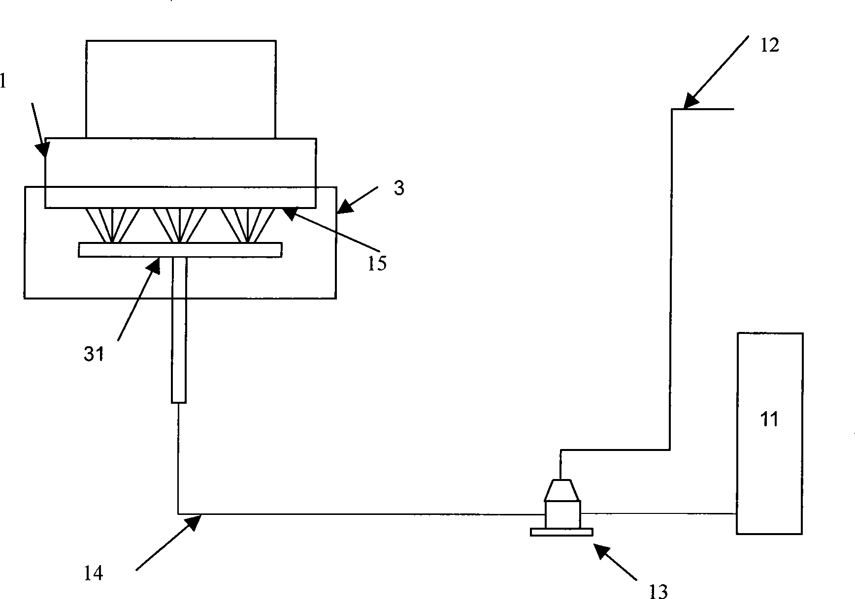
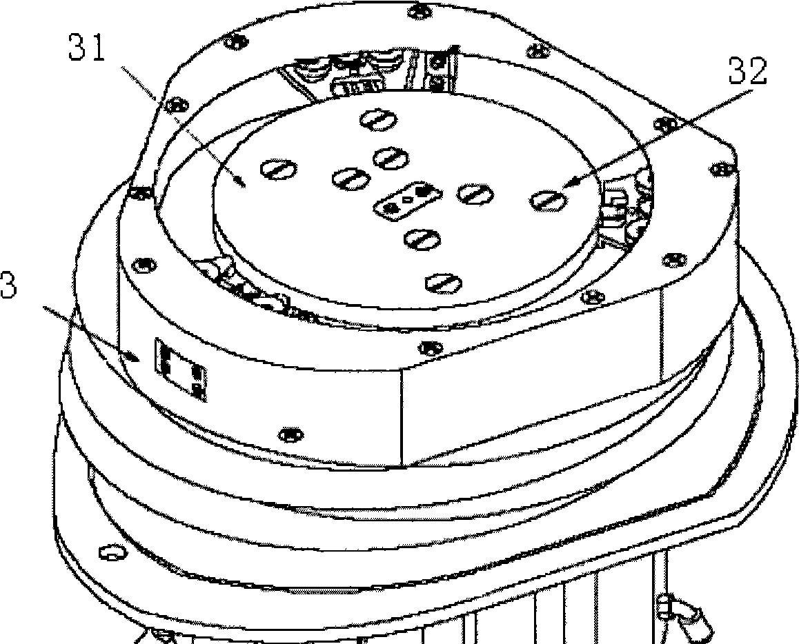
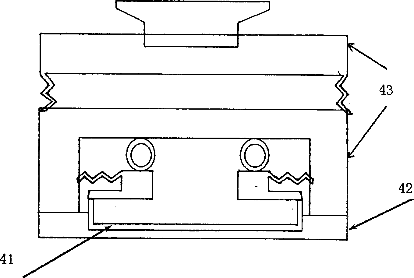
[0014] One embodiment of the CMP equipment grinding head cleaning device of the present invention is as follows: Figure 4 As shown, it includes a water supply module 11, a grinding head cleaning control air circuit 12, a pneumatic water valve 13, a water supply pipe 14 for the loading platform, and a grinding head loading and unloading device 3. The grinding head loading and unloading device 3 is as follows figure 2 As shown, the inner bottom of the device is a silicon chip carrier platform 31, and eight pure water nozzles 32 are distributed on the carrier platform 31, and the pure water nozzles are connected with the carrier platform water supply pipe 14; it also includes a pneumatic water valve 223 and a peripheral cleaning water supply pipe 24 One end of the peripheral cleaning water supply pipe 24 is a peripheral cleaning nozzle, and the grinding head cleaning control air circuit 12 simultaneously controls the opening and closing of the pneumatic water valve one 13 and th...


PUM


Abstract

The invention discloses a device used for cleaning the grinding head of CMP equipment, comprising a water supply module, a grinding head cleaning control air passage, a pneumatic water valve 1, a bearing platform water supply pipe, and a grinding head assembly/disassembly device; wherein, the internal bottom of the grinding head assembly/disassembly device is a silicon plate bearing platform which is provided with pure water nozzles which are communicated with the bearing platform water supply pipe; the device also comprises a pneumatic water valve 2 and a peripheral cleaning water supply pipe; the grinding head cleaning control air passage controls the openness and closeness of the pneumatic water valve 1 and the pneumatic water valve 2 at the same time, thus communicating or preventing the pure water in the water supply module from entering the bearing platform water supply pipe and the peripheral cleaning water supply pipe; one end of the peripheral cleaning water supply pipe is a peripheral cleaning nozzle which is additionally arranged beside the grinding head assembly/disassembly device; furthermore, the outlet of the nozzle faces inwards; the gushed pure water can wash the grinding head peripheral area above the grinding head assembly/disassembly device. The device used for cleaning the grinding head of CMP equipment can reduce the frequency and time of maintenance operation of CMP equipment, and can reduce the possibility that the grains exceed the standard and the product is scraped.

Description

technical field [0001] The invention belongs to the field of semiconductor manufacturing, and relates to cleaning and maintenance of semiconductor equipment, in particular to a cleaning device for a grinding head of a CMP equipment. Background technique [0002] CMP (Chemical Mechanical Polishing) equipment is an abbreviation for chemical mechanical polishing equipment in the semiconductor industry. The cleaning device of the grinding head of the existing CMP equipment is as figure 1 shown. Including water supply module 11, grinding head cleaning control air circuit 12, pneumatic water valve 13, water supply pipe 14 for loading platform, grinding head loading and unloading device 3, grinding head loading and unloading device 3 such as figure 2 As shown, the inner bottom of the device is a silicon chip carrier platform 31, and eight ultrapure water nozzles 32 are distributed on the carrier platform 31. The ultrapure water nozzles are connected with the carrier platform wat...

Claims


Application Information

Patent Timeline
Patent Type & Authority Applications(China)
IPC IPC(8): B24B37/04B24B55/00H01L21/304B24B37/34
Inventor 祝志敏瞿治军
Owner SHANGHAI HUA HONG NEC ELECTRONICS
Why Eureka
Try Eureka