An improved non-zero dispersion-shifted single-mode fiber with large mode field distribution

A non-zero dispersion, single-mode optical fiber technology, applied in the direction of multi-layer core/clad optical fiber, clad optical fiber, optical waveguide light guide, etc., can solve the problems of increased additional loss, increased reflection, etc., to achieve improved PMD performance, Effect of improving stress distribution and stabilizing PMD performance

Active Publication Date: 2012-02-22
HANGZHOU FUTONG COMM TECH CO LTD +1
View PDF9 Cites 2 Cited by
  • Summary
  • Abstract
  • Description
  • Claims
  • Application Information

AI Technical Summary

Problems solved by technology

[0007] In the actual long-distance optical fiber transmission system, it is usually necessary to connect different optical fibers to form a communication link. The refractive index distribution of the non-zero dispersion-shifted fiber is more complicated than that of the standard single-mode fiber. When they are together, due to the mismatch between the mode length and diameter of each other and the geometric parameters of the fiber, it often leads to increased reflection and increased additional loss. The longer the link, the more contacts, the greater the cumulative effect, and serious may cause unacceptable bit errors. Rate

Method used


Image

  • An improved non-zero dispersion-shifted single-mode fiber with large mode field distribution
  • An improved non-zero dispersion-shifted single-mode fiber with large mode field distribution
  • An improved non-zero dispersion-shifted single-mode fiber with large mode field distribution

Examples


Embodiment 1

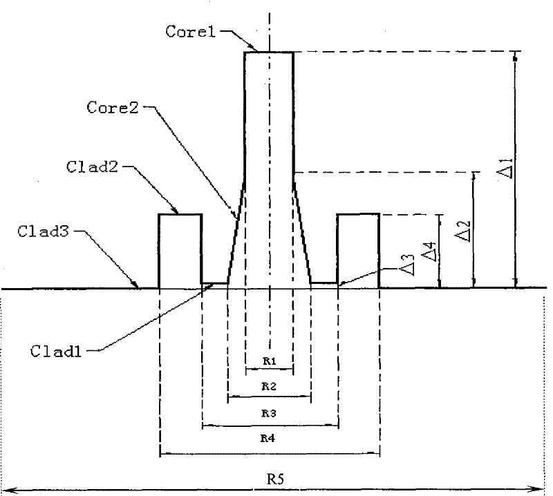
[0040] Such as figure 1 Shown is a kind of optical fiber waveguide refractive index distribution curve of the present invention, the following is a set of relative refractive index difference distribution parameters:

[0041] The parameters of the inner core layer Core1 are: Δn1 is about 0.60%, R1 is about 3.6um,

[0042] The parameters of the outer core layer Core2 are: Δn2 is about 0.25%, R2 is about 7.6um,

[0043] The parameters of the inner cladding Clad1 are: Δn3 is about 0.02%, R3 is about 12.8um,

[0044] The parameters of the ring core cladding Clad2 are: Δn4 is about 0.21%, R4 is about 17.2um,

[0045] The parameters of the outer cladding (that is, the outermost layer) Clad3 are: Δnc is about 0.00%, R5 is 125um,

[0046] The outer cladding Clad3 is a pure silica glass layer, and its refractive index is nc (Δnc=0),

[0047] The gradient distribution of the refractive index of the outer core layer Core2 satisfies the formula: n(r)=nc*[1-2Δ(r / r2) a ] 1 / 2 , where r...

Embodiment 2

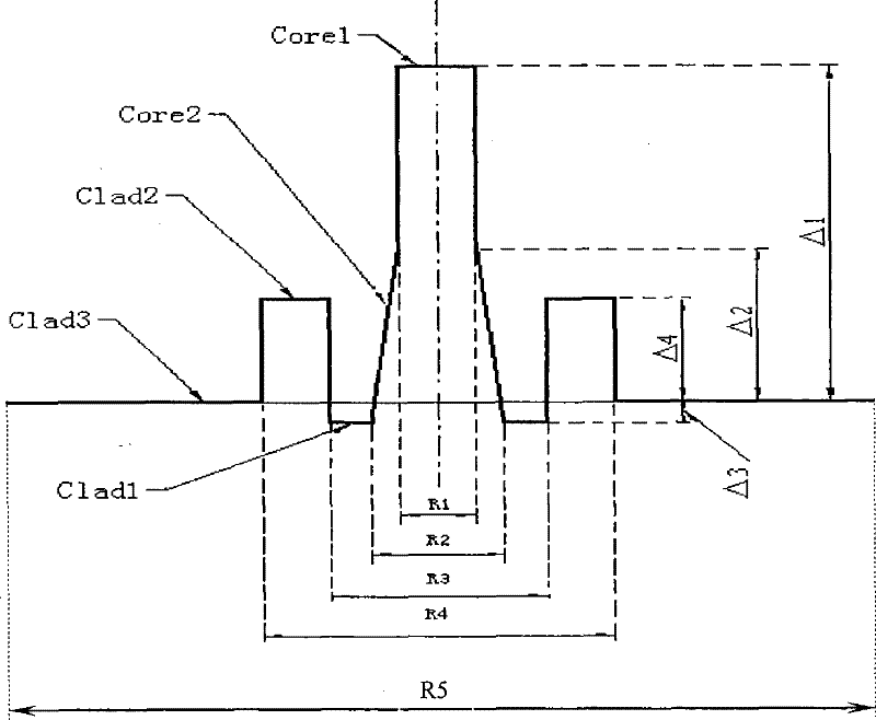
[0061] according to figure 2 The shown optical fiber waveguide refractive index distribution curve, the following is a set of relative refractive index difference distribution parameters:

[0062] The parameters of the inner core layer Core1 are: Δn1 is about 0.58%, R1 is about 3.8um,

[0063] The parameters of the outer core layer Core2 are: Δn2 is about 0.24%, R2 is about 7.8um,

[0064] The parameters of the inner cladding Clad1 are: Δn3 is about -0.05%, R3 is about 13.0um,

[0065] The parameters of the ring core cladding Clad2 are: Δn4 is about 0.23%, R4 is about 18.2um,

[0066] The parameters of the outer cladding Clad3 are: Δnc is about 0.00%, R5 is about 125um,

[0067] The outer cladding Clad3 is a pure silica glass layer, and its refractive index is nc,

[0068] The gradient distribution of the refractive index of the outer core layer Core2 satisfies the formula: n(r)=nc*[1-2Δ(r / r2) a ] 1 / 2 , where r1≤r≤r2, r is the radius variable of the outer core layer, r1...

Embodiment 3

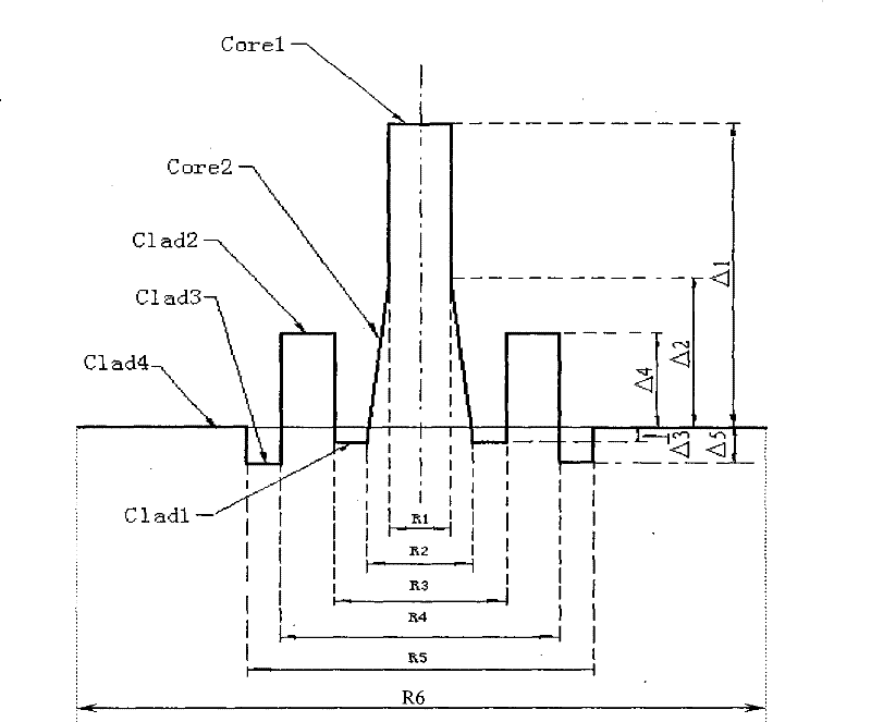
[0083] according to image 3 The shown optical fiber waveguide refractive index distribution curve, the following is a set of relative refractive index difference distribution parameters:

[0084] The parameters of the inner core layer Core1 are: Δn1 is about 0.56%, R1 is about 4.0um,

[0085] The parameters of the outer core layer Core2 are: Δn2 is about 0.22%, R2 is about 8.0um,

[0086] The parameters of the inner cladding Clad1 are: Δn3 is about -0.07%, R3 is about 13.6um,

[0087]The parameters of the first ring core cladding Clad2 are: Δn4 is about 0.22%, R4 is about 19.2um,

[0088] The parameters of the second ring core cladding Clad3 are: Δn5 is about 0.-08%, R5 is about 20.8um,

[0089] The parameters of the outermost layer, that is, the outer cladding layer Clad4 are: Δnc is about 0.00%, R6 is 125um,

[0090] The cladding layer Clad4 is a pure silica glass layer with a refractive index nc (Δnc=0),

[0091] The gradient distribution of the refractive index of th...


PUM


Abstract

The invention is an improved non-zero dispersion-shifted single-mode optical fiber with large mode field distribution, which includes an optical fiber core layer and a cladding layer surrounding the optical fiber core layer, and the optical fiber core layer includes inner core layers with different refractive indices and The outer core layer surrounding the inner core layer, the refractive index of the outer core layer is gradually distributed, and the cladding layer includes an inner cladding layer, a ring core cladding layer and an outer cladding layer with different refractive indices from the inside to the outside, and the outer cladding layer is pure silica glass layer, the refractive index distribution of the fiber core layer is n1>n2>nc, and the cladding refractive index distribution is n4>n3>nc or n4>nc>n3. It has low nonlinear color effect characteristics, that is, large effective area, optimized dispersion and low dispersion slope, which can effectively solve the nonlinear problem and polarization mode dispersion problem affecting high-speed communication, reduce the dispersion management cost of the system, and have low Splice loss, suitable for large-capacity, high-speed, long-distance transmission systems.

Description

technical field [0001] The invention relates to a non-zero dispersion-shifted single-mode optical fiber designed for a large-capacity, high-speed, long-distance transmission system. The fiber has improved characteristics of low nonlinear effect, that is, large mode field distribution (effective area), optimized chromatic dispersion and low dispersion slope, and has low polarization mode dispersion, low loss and excellent bending resistance, and is compatible with Fiber splicing has the advantages of low splicing loss, suitable for large-capacity, high-speed, long-distance dense wavelength division multiplexing DWDM system transmission, large effective area is conducive to reducing nonlinear effects, and low dispersion slope is conducive to the reduction of dispersion Comprehensive management to meet the long-distance transmission of C+L and S+C+L bands. Background technique [0002] With the development of optical fiber communication technology, especially the mature applic...

Claims


Application Information

Patent Timeline
Patent Type & Authority Patents(China)
IPC IPC(8): G02B6/036G02B6/02
Inventor 吴金东卢卫民吴海港张立永
Owner HANGZHOU FUTONG COMM TECH CO LTD
Why Eureka
Try Eureka