Display device and electronic apparatus

A technology for display devices and display areas, which is applied in identification devices, radiation control devices, static indicators, etc., and can solve the problems of adverse effects on display quality, inability to eliminate reflected light noise of display devices in real time, and difficulty in use, etc.

Inactive Publication Date: 2009-06-03
JAPAN DISPLAY INC
View PDF5 Cites 29 Cited by
  • Summary
  • Abstract
  • Description
  • Claims
  • Application Information

AI Technical Summary

Problems solved by technology

However, since the infrared cut filter itself is colored, the display quality itself is adversely affected, which makes it difficult to use this method
[0017] Furthermore, in the above-mentioned systems and systems for implementing touch panels, image sensors, etc. by using light from the backlight and reflected from a detection object such as a finger, there is a problem that noise of reflected light in a display device may not be eliminated immediately
[0018] Furthermore, in the above-mentioned system based on light from the backlight and the imaging system based on ambient light, it may not be possible to remove disturbing noise from the display section in real time
[0019] Also, for these reasons, it may not be possible to realize a high-reliability system that has good temperature characteristics and can withstand changes over time

Method used


Image

  • Display device and electronic apparatus
  • Display device and electronic apparatus
  • Display device and electronic apparatus

Examples


no. 1 example

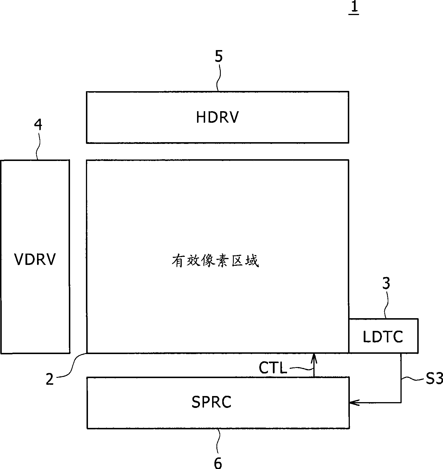
[0068] figure 2 is a block diagram showing a configuration example of the liquid crystal display device according to the first embodiment of the present invention.

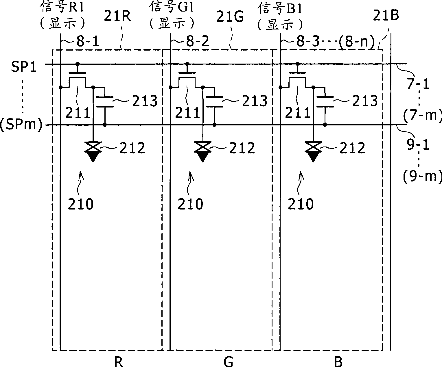
[0069] Figure 3A ~Figure 3C is showing the figure 2 Diagram of a configuration example of an effective pixel area unit in a liquid crystal display device: Figure 3A Showing a matrix arrangement of cells, FIG. 3B is a plan view, and FIG. 3C is a cross-sectional view.

[0070] Figure 4 is a diagram showing a configuration example of the photodetection circuit according to the present embodiment.

[0071] Such as figure 2 As shown, a liquid crystal display device 1 includes an effective display area unit (image display portion) 2 as a display unit, a photodetector (LDTC) 3, a vertical drive circuit (VDRV) 4, a horizontal drive circuit (HDRV) 5, and a signal processing circuit (SPRC)6.

[0072] The liquid crystal display device 1 of the present embodiment is configured to be able to change the surface bri...

no. 2 example

[0215] Figure 22 is a block diagram showing a configuration example of a liquid crystal display device according to a second embodiment of the present invention.

[0216] Figures 23A to 23C are diagrams showing the Figure 22 Diagrams of configuration examples of effective pixel area units in a liquid crystal display device of : FIG. 23A shows a matrix arrangement of units, FIG. 23B is a plan view, and FIG. 23C is a cross-sectional view.

[0217] A liquid crystal display device 1A of the second embodiment is different from the above-described liquid crystal display device 1 of the first embodiment. Specifically, in the second embodiment, the photodetector 3 is formed adjacent to the effective display area unit 2 outside the effective display area unit 2 (in the non-display area outside the effective area of ​​the display area unit). In contrast to an embodiment, the light detector 3A is integrally formed with the effective display area unit 2A.

[0218] Such as Figure 22...


PUM


Abstract

Disclosed herein are a display device and electronic apparatus; wherein the display device includes a first light sensor unit configured to include a light-receiving element and detect intensity of ambient light to a display area; a second light sensor unit configured to include a light-receiving element and be provided with an infrared filter disposed on an optical path to the light-receiving element; and a signal processor configured to execute difference processing for a detection signal of the first light sensor unit and a detection signal of the second light sensor unit, wherein the infrared filter is formed by stacking at least two kinds of color filters.

Description

[0001] Cross References to Related Applications [0002] The present invention contains subject matter related to Japanese Patent Application JP 2007-304341 filed in the Japan Patent Office on Nov. 26, 2007, the entire content of which is hereby incorporated by reference. technical field [0003] The present invention relates to a display device and electronic equipment including a photosensor in a display pixel portion or on a frame of the display pixel portion. Background technique [0004] There is known a technology in which the brightness of ambient light is detected by a light sensor, thereby increasing the screen brightness when the ambient brightness is high and decreasing the screen brightness when the ambient brightness is low. Enhance the visibility of the screen by using this technology. Furthermore, if an image is displayed by using a backlight system such as one of liquid crystal display devices, the power consumption of the backlight system is reduced by this...

Claims


Application Information

Patent Timeline
Patent Type & Authority Applications(China)
IPC IPC(8): G09F9/30H01L27/146G09F9/35G02F1/1335G02F1/13
CPCG02F1/13318G02F1/133G09G3/36
Inventor 坂井荣治中西贵之上岛诚司
Owner JAPAN DISPLAY INC
Why Eureka
Try Eureka