ITO film laser engraving device and method

A laser etching, thin film technology, applied in laser welding equipment, welding equipment, metal processing equipment and other directions, can solve the problems of poor linearity of conductive film layers, increase equipment cost, reduce service life, etc., to reduce the impact of human operation, Ease of circuit design, effect of protecting substrate materials

Active Publication Date: 2011-09-28
HANS LASER TECH IND GRP CO LTD
View PDF0 Cites 1 Cited by
  • Summary
  • Abstract
  • Description
  • Claims
  • Application Information

AI Technical Summary

Problems solved by technology

[0004] The use of wet chemical reagent etching processing requires additional cleaning, wastewater treatment and other equipment that occupy a large area, high production costs, low service life, poor linearity of the conductive film layer, and the need to increase the processing and use area, etc.
Etching will leave photoresist on the surface of the substrate, and immersion in the etching solution will damage the surface and reduce the service life; the solution used in the etching process will inevitably add cleaning, wastewater treatment and other procedures, which will increase equipment costs; the step of removing photoresist after etching will cause ITO The linearity of the conductive line is poor, which affects the stability and consistency of the performance
[0005] With the continuous development of the touch screen and liquid crystal display industry, the demand for the performance of ITO film substrates has been continuously improved, and the processing method of ITO films has also changed. The processing efficiency is low, and the traditional motor is used to move the platform, which cannot guarantee the linearity of processing

Method used


Image

  • ITO film laser engraving device and method
  • ITO film laser engraving device and method
  • ITO film laser engraving device and method

Examples


Embodiment Construction

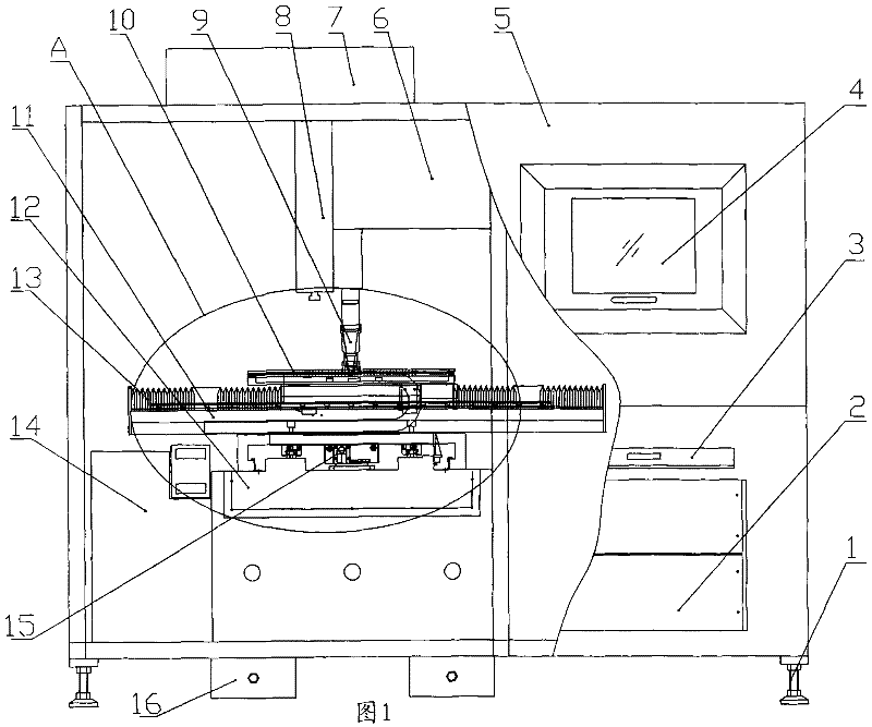
[0031] Such as Figure 1 to Figure 3 As shown, the laser etching equipment of the present invention includes a foot support adjustment bolt 1, an industrial computer 2, a keyboard and mouse drawer box 3, a display system 4, a frame 5, a laser generator 6, a fan filter unit (FFU) 7, and a Axis motion system 8, cutting head 9, suction disc 10, X-axis motion system 11, Y-axis motion system 12, dust cover 13, electrical control cabinet 14, linear motor 15, shockproof pad iron 16, sliding wheel 17, red light Inductance device 18, automatic door protection device 19, cylinder shaft 20, casters 21;

[0032] The industrial computer 2, the laser generator 6, the Z-axis motion system 8, the display system 4, the fan filter unit (FFU) 7, and the automatic door protection device 19 are all installed on the frame 5, and the cutting head 9 is installed on the Z axis. On the axis motion system 8, it is located above the adsorption disc 10, and the adsorption disc 10 is fixedly installed on ...


PUM

PropertyMeasurementUnit
wavelengthaaaaaaaaaa

Abstract

The present invention discloses ITO film laser etching equipment and a method. The equipment comprises a machine frame, a work control machine, a display system, a laser generator, a cutting head, an adsorbing disk, an X-axis moving system, a Y-axis moving system and a Z-axis moving system, wherein the work control machine, the laser generator, the display system and the Z-axis moving system are all arranged on the machine frame, the cutting head is arranged on the Z-axis moving system, the adsorbing disk is fixed on the X-axis moving system and positioned above the Y-axis moving system, the X-axis moving system is arranged on the Y-axis moving system and is intersected into a cross shape and the Y-axis moving system is fixedly arranged on the machine frame. The etching method comprises the following steps: placing an etched product on a workbench of the laser etching equipment and positioning the etched product; and controlling the laser etching equipment to etch the etched product according to a preset graph. The laser etching equipment has high line etching efficiency and good linearity for the ITO films.

Description

【Technical field】 [0001] The invention relates to the technical field of laser cutting, in particular to an ITO thin film laser etching device and an etching method. 【Background technique】 [0002] ITO film is indium tin oxide semiconductor transparent conductive film, which is coated on organic thin film PET, glass (sodium calcium Na-Ca glass) or rigid plastic (acrylic plate with hardened surface) substrate, generally only a few meters thick. Kiloangstroms (300-500nm), this indium tin oxide thin film has excellent characteristics such as low resistivity, high visible light transmittance and high ultraviolet light reflectance. After the substrate coated with ITO film is scored, the upper layer and the lower layer are combined, and the X-axis and Y-axis are respectively wired. The middle of the two layers of circuits is supported by a very small insulating point as a spacer. Wait for any material to exert pressure on the upper conductive film, causing a short circuit between...

Claims


Application Information

Patent Timeline
Patent Type & Authority Patents(China)
IPC IPC(8): B23K26/08B23K26/42B23K26/14B23K26/40
Inventor 高云峰陈夏弟郑其锋倪鹏玉程文胜李世印王文王小博
Owner HANS LASER TECH IND GRP CO LTD
Why Eureka
Try Eureka