Method for dissolving biological cell in sludge and use thereof

A biological cell and sludge technology, which is applied in the direction of oxidation treatment of sludge, can solve the problems of low ozone treatment sludge dissolution efficiency, poor ozone solubility and stability, and increased ozone dosage, so as to solve a large amount of residual sewage. Mud problem, realization of volume reduction, high internal pressure effect

Inactive Publication Date: 2009-06-17
TSINGHUA UNIV +1
View PDF4 Cites 18 Cited by
  • Summary
  • Abstract
  • Description
  • Claims
  • Application Information

AI Technical Summary

Problems solved by technology

One is that the solubility and stability of ozone in water are poor, the utilization rate of ozone is not high, and the cost of ozone generation is higher, resulting in higher cost of ozone treatment; the other is that the dissolution efficiency of ozone treatment sludge is generally not high ( Bougrier, C., Albasi, C. et al., Effect

Method used


Image

  • Method for dissolving biological cell in sludge and use thereof
  • Method for dissolving biological cell in sludge and use thereof
  • Method for dissolving biological cell in sludge and use thereof

Examples


Embodiment 1

[0038] Embodiment 1, the method utilizing ozone microbubbles to dissolve biological cells in sludge

[0039] l. Ozone Micro Bubble Generator

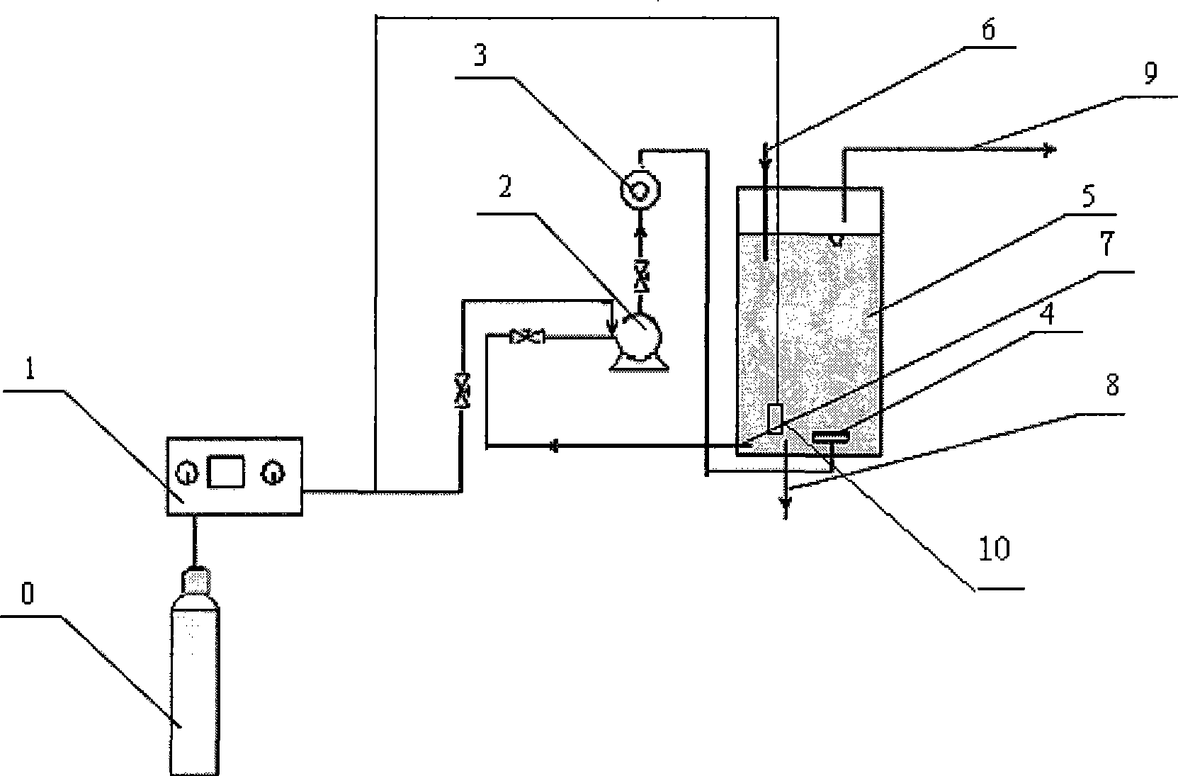
[0040] Ozone microbubble generators, such as figure 2 As shown, it is mainly composed of an ozone generator 1 and a micron bubble generator. The micro-bubble generator is formed by connecting a water pump 2, a cyclotron 3 and a disperser 4 through pipelines.

[0041] The ozone micro-bubble generating device also includes an oxygen cylinder 0 containing oxygen, which is a raw material for producing ozone, and a reactor 5 providing a reaction space for sludge solution and ozone micro-bubbles. The reactor 5 has an input 6 and 3 outputs. The input port 6 is used to input the sludge solution into the reactor 5 . The output end 7 is used to input the sludge solution into the water pump 2, the output end 8 is used to discharge the dissolved sludge, and the output end 9 is a channel for exhaust gas.

[0042] The input end of the ozone gen...

Embodiment 2

[0080] Embodiment 2, the relationship between the COD dissolution rate of sludge and the solid dissolution rate and the amount of ozone added

[0081] The apparatus, experimental method and sludge solution used in this experiment are the same as in Example 1. Sludge solutions 1-a, 1-b, 1-c, 1-d, 1-e, 2-a and 2-b are treated with the micro-bubble system of Example 1, and passed into sludge solution 1-b` The common bubble system of Example 1 was used for the treatment.

[0082] Samples were taken to measure the total COD of the sludge solution, the COD of the supernatant, TSS and VSS and other indicators.

[0083] The dissolution rate of sludge is measured by COD dissolution rate (S COD ) and solid dissolution rate (S TSS ) to represent.

[0084] S COD =(COD p0 -COD p ) / COD p0

[0085] S TSS =(TSS 0 -TSS) / TSS 0

[0086] COD p Indicates the COD (mg / L) of the solid part in the sludge mixture, TSS indicates the total suspended solids concentration (mg / L), and the subs...


PUM


Abstract

The invention discloses a method for dissolving biological cells in sludge and application thereof. The method for dissolving the biological cells in the sludge comprises: micron bubbles of ozone are introduced into the sludge to dissolve the biological cells in the sludge. The method for dissolving the biological cells in the sludge can be used for sludge reduction; the specific method comprises: the micron bubbles of the ozone are introduced into a sludge solution for sludge reduction. The method greatly improves the dissolution rate of the sludge; the initial sludge concentration is within the range of between 1,500 and 6,000 mg/L; when the addition amount of the ozone (the amount of the ozone introduced into the sludge solution) is between 0.06 and 0.16g O3/g TSS, the COD dissolution rate and solid dissolution rate of the sludge can reach 25 to 50 percent and 15 to 35 percent respectively; the utilization rate of ozone gas is above 99 percent; and the ozone concentration in tail gas can be controlled within the range allowed by emission.

Description

technical field [0001] The invention relates to a method for dissolving biological cells in sludge and its application in the technical field of sewage treatment. Background technique [0002] The wastewater biological treatment technology represented by the activated sludge method will produce a large amount of excess sludge, and the disposal cost of excess sludge accounts for about 40-60% of the total operating cost of the sewage treatment plant. It is an urgent problem to be solved in the field of sewage treatment to study the technology of excess sludge reduction. Excess sludge reduction can be achieved by adopting new reactors or operations to reduce sludge generation at the source. For example, the aerobic-anaerobic repeated coupling sewage treatment invented by Feng Quan et al. (Xing Xinhui, Feng Quan, Lou Kai, Luo Mingfang, authorized invention patent ZL200310121766.7; Feng Quan, Xing Xinhui, Liu Zehua, using excess sludge reduction Research progress of wastewater ...

Claims


Application Information

Patent Timeline
IPC IPC(8): C02F11/06
Inventor 邢新会初里冰闫桑田于安峰冯权孙旭临本杰明
Owner TSINGHUA UNIV
Why Eureka
Try Eureka